How to Print & Assemble The SPACESHIP-S2

How to print the SPACESHIP-S2

If you want to save this How-To instruction as a pdf file (and print it out later if needed), simply copy the URL of this page and paste it to https://www.printfriendly.com/ . Printfriendly will generate a printer-friendly pdf of the page with all the texts and images for you.

All of the STL files are really straight forward to print. All you need to do is load them into your slicer software (I use Cura), select your desirable settings (e.g. layer height, infill percentage, etc.) and slice the parts. I used 0.4mm nozzle and 0.2mm layer height to print large parts and 0.25mm nozzle and 0.1mm layer height to print small parts (e.g. Raptor engines & RVac engines)

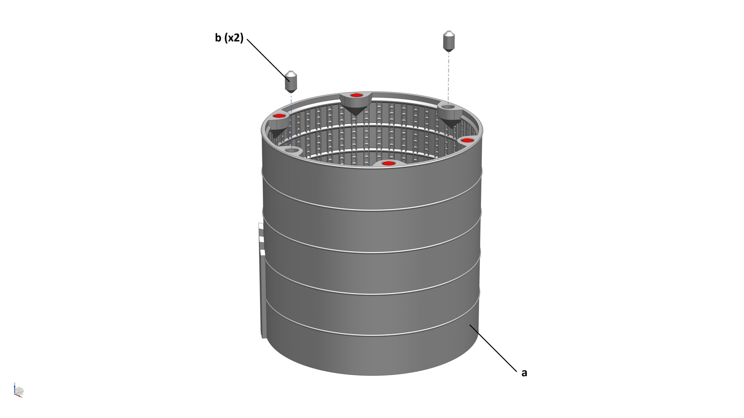
Please note: I already saved the STL for each part in the orientation I printed them on my FDM printer. Hence, when you load the STL in your slicer software, you don’t need to orientate them again, unless you want to try to print them in a different orientation.

Below are some tips

  • All magnet holes can be printed without support regardless of their positions/orientations on the model. Please don’t generate support for these holes (unless you really need to). Otherwise, you may struggle to remove support inside the holes due to restricted access. The easiest way to stop Cura from generating support inside these magnet holes is to use support blocker to cover the holes.

  • All stiffeners (inside the Skirt Section, Thrust Dome Section, Forward Dome Section and Nose Cone Fairing Section) can be printed without support. To stop Cura from generating support for them, you can select ‘Touching Buildplate’ in the ‘Support Placement’ box. You don’t actually need any support at all to print most parts (since they are designed specifically for FDM printers), especially if your printers are good at bridging so just simply untick the box ‘Generate Support’.

  • This Starship model is designed in such a way to allow you to assemble and disassemble the model into piece part level, because almost every part is held together by magnets. However, if you prefer to glue everything, or some parts, together, that’s also fine – but please be aware that if you do, it may be difficult to update the model later on.

  • There is an STL in folder ‘STEP 01’ called ‘Starship Assembly_S2.stl’. If you load this file, you’ll see the fully assembled STARSHIP-S2 model. This will help you understand where each and every part is fitted on the model.

  • There are two ways to print the Nose Cone.
    (1) Print the entire Nose Cone in one piece, this means the “SN24 logo”, “SpaceX logo”, and the 6x hexagon-shaped Comms Antenna in the front of the Nose Cone will be the same colour as the rest of the Nose Cone. Hence, if you want those features to be black, you’ll need to paint them later
    (2) Print the Nose Cone on a dual-extrusion printer. To do this, in STEP 08, load the 2 STL files in the “2 colour version” folder in Cura, assign each nozzle to each file, then select both and merge them together. Now, you can print all the black features above with one nozzle and the rest of the Nose Cone with the other nozzle

  • When you slice all the main ring segment parts of the model in Cura, align the seam to the back side so the part will look perfect from the front side (which all the features are visible). Once you install the Heat Shield Tiles on these main parts later on, the seams will be covered so they remain hidden

  • This model is designed at 1:96 scale and I highly recommend you to print at this scale to achieve the highest quality. However, if you decided to print it at a smaller scale, please be aware that the magnets I selected for this model will no longer fit  and you will have to glue the parts together.

How to assemble this model?

So now you’ve got all your parts printed? Great! Let’s assemble the model. I’ll take you through the assembly process step by step but before that, you need to purchase some items:

  • 5mm dia x 3mm thick N42 Neodymium magnets (LINK) | Qty: 67-off
  • 3mm dia x 2mm thick N42 Neodymium (LINK) | Qty: 80-off
  • Super glue (LINK) | Qty: 1 bottle

STEP 1: ‘Dry’ assemble the model

At this step, all I want you to do is try to stack all the parts together to get a good understanding of where they are located. Because there are a lot of magnets you need to fit during the assembly process, doing this first step will give you an idea of how to fit the magnets in each part correctly. Please use the ‘Starship Assembly_S2.stl’ and the photos below if required.

STEP 2: Assemble the Skirt Section

Parts required (refer to the photos below)

  • 1x Skirt Section_S2 (a)
  • 2x Location Pin_S2 (b)
  • 10x Magnets (3mm dia x 2mm thick) (highlighted in RED)
  • 4x Magnets (5mm dia x 3mm thick) (highlighted in RED)

Assembly process

  1. STEP 2a: Glue 4x 5mm dia x 3mm thick magnets into their locations on the Skirt Section
  2. STEP 2b: Glue 10x 3mm dia x 2mm thick magnets into their locations on the Skirt Section
  3. STEP 2c: Glue 2x Location Pins to 2 holes located on the top face of the Skirt Section

STEP 3: Assemble the Thrust Dome Section

Parts required (refer to the photos below)

  • 1x Thrust Puck_S2 (a)
  • 1x Thrust Dome Section_S2 (b)
  • 2x Location Pin_S2 (c)
  • 10x Magnets (3mm dia x 2mm thick) (highlighted in RED)
  • 16x Magnets (5mm dia x 3mm thick) (highlighted in RED)

Assembly process

  1. STEP 3a: Glue 6x 5mm dia x 3mm thick magnets into their locations on the bottom face of the Thrust Puck
  2. STEP 3b: Glue 10x 3mm dia x 2mm thick magnets into their locations on the Thrust Dome Section
  3. STEP 3c: Glue 8x 5mm dia x 3mm thick magnets into their locations on the top & bottom faces of the Thrust Dome Section
  4. STEP 3d: Glue 2x 5mm dia x 3mm thick magnets into their locations on the front face of the Thrust Dome Section
  5. STEP 3e: Glue 2x Location Pins to 2 holes located on the top face of the Thrust Dome Section
  6. STEP 3f: Glue the Thrust Puck to the Thrust Dome Section. IMPORTANT: these two parts must be aligned correctly to each other!!! – see pics below for reference

STEP 4: Assemble the LOX Tank Section

Parts required (refer to the photos below)

  • 1x LOX Tank Section_S2 (a)
  • 2x Location Pin_S2 (b)
  • 6x Magnets (3mm dia x 2mm thick) (highlighted in RED)
  • 8x Magnets (5mm dia x 3mm thick) (highlighted in RED)

Assembly process

  1. STEP 4a: Glue 8x 5mm dia x 3mm thick magnets into their locations on the LOX Tank Section
  2. STEP 2b: Glue 6x 3mm dia x 2mm thick magnets into their locations on the LOX Tank Section
  3. STEP 2c: Glue 2x Location Pins to 2 holes located on the top face of the LOX Tank Section

STEP 5: Assemble the Common Dome Section

Parts required (refer to the photos below)

  • 1x Common Dome Section_S2 (a)
  • 2x Location Pin_S2 (b)
  • 8x Magnets (5mm dia x 3mm thick) (highlighted in RED)

Assembly process

  1. STEP 5a: Glue 8x 5mm dia x 3mm thick magnets into their locations on the Common Dome Section
  2. STEP 5b: Glue 2x Location Pins to 2 holes located on the top face of the Common Dome Section

STEP 6: Assemble the Forward Dome Section

Parts required (refer to the photos below)

  • 1x Forward Dome Section_S2 (a)
  • 2x Location Pin_S2 (b)
  • 2x Forward Dome Cap_S2 (c)
  • 2x Magnets (3mm dia x 2mm thick) (highlighted in RED)
  • 8x Magnets (5mm dia x 3mm thick) (highlighted in RED)

Assembly process

  1. STEP 6a: Glue 8x 5mm dia x 3mm thick magnets into their locations on the Forward Dome Section
  2. STEP 6b: Glue 2x 3mm dia x 2mm thick magnets into their locations on the Forward Dome Section
  3. STEP 6c: Glue 2x Location Pins to 2 holes located on the top face of the Forward Dome Section. Press fit the Forward Dome Caps (you can also glue two halves of the cap together)

STEP 7: Assemble the Nose Cone Fairing Section

Parts required (refer to the photos below)

  • 1x Nose Cone Fairing Section_S2 (a)
  • 2x Location Pin_S2 (b)
  • 8x Magnets (5mm dia x 3mm thick) (highlighted in RED)

Assembly process

  1. STEP 7a: Glue 8x 5mm dia x 3mm thick magnets into their locations on the Nose Cone Fairing Section
  2. STEP 7b: Glue 2x Location Pins to 2 holes located on the top face of the Nose Cone Fairing Section

STEP 8: Assemble the Nose Cone Section

Parts required (refer to the photos below)

  • 1x Nose Cone Section_S2
  • 8x Magnets (3mm dia x 2mm thick) (highlighted in RED)
  • 5x Magnets (5mm dia x 3mm thick) (highlighted in RED)

Assembly process

  1. STEP 8a: Glue 5x 5mm dia x 3mm thick magnets into their locations on the Nose Cone Section
  2. STEP 8b: Glue 8x 3mm dia x 2mm thick magnets into their locations on the Nose Cone Section

STEP 9: Assemble the Raptor/RVac Engines

Parts required (refer to the photos below)

  • 3x Raptor Engine_S2 (a)
  • 3x Raptor Engine Shield_S2 (b)
  • 3x RVac Engine_S2 (c)
  • 6x Magnet (5mm dia x 3mm thick) (highlighted in RED)

Assembly process

  1. STEP 9a: Glue 1x magnets (5mm dia x 3mm thick) into the magnet hole on each Raptor Engine Shield, then glue the Raptor Engine Shields and the Raptor Engines together
  2. STEP 9b: Glue 1x magnets (5mm dia x 3mm thick) into the magnet hole on each RVac Engine

STEP 10: Stack Thrust Dome Section

Parts required (refer to the photos below)

  • 1x Skirt Section from STEP 2 (a)
  • 1x Thrust Dome Section from STEP 3 (b)
  • 3x Raptor Engine from STEP 9 (c)
  • 3x RVac Engine from STEP 9 (d)
  • 3x Engine Floor (e)
  • 6x Magnet (3mm dia x 2mm thick) (highlighted in RED)

Assembly process

  1. STEP 10a: Glue 2x magnets (3mm dia x 2mm thick) into the magnet holes on each Engine Floor
  2. STEP 10b: Install 3x Raptor Engines on the Thrust Puck
  3. STEP 10c: Install 3x RVac Engines on the Thrust Puck
  4. STEP 10d: Install 3x Engine Floors on the Thrust Dome Section
  5. STEP 10e: Stack Thrust Dome Section on Skirt Section

STEP 11: Install plumbing to Thrust Dome Section

Parts required (refer to the photos below)

  • 1x Sub-Assembly from STEP 10 (a)
  • 1x LOX Fill_Drain Pipe_S2 (b)
  • 1x CH4 Fill_Drain Pipe_S2 (c)
  • 1x CH4 Fill_Drain Pipe Extension_S2 (d)
  • 1x LOX 3-way Joint_S2 (e)
  • 1x CH4 6-way Joint_S2 (f)
  • 4x Magnet (3mm dia x 2mm thick) (highlighted in RED)

Assembly process

  1. STEP 11a: Glue 1x magnets (3mm dia x 2mm thick) into the magnet hole on the CH4 Fill_Drain Pipe Extension (d)
  2. STEP 11b: Glue 3x magnets (3mm dia x 2mm thick) into the magnet holes on the CH4 6-way Joint (f)
  3. STEP 11c: Glue the LOX Fill_Drain Pipe (b) to the Thrust Puck
  4. STEP 11c: [Optional] Glue the CH4 Fill_Drain Pipe (c) to the Thrust Puck
  5. STEP 11c: Install the pipes into the Thrust Dome Section as per diagrams/photos below

STEP 12: Stack LOX Tank Section

Parts required (refer to the photos below)

  • 1x Sub-Assembly from STEP 11 (a)
  • 1x LOX Tank Section from STEP 4 (b)
  • 1x CH4 Header Tank Downcomer (Bottom)_S2 (c)
  • 1x CH4 Main Tank Downcomer (Bottom)_S2 (d)
  • 3x Magnet (3mm dia x 2mm thick) (highlighted in RED)

Assembly process

  1. STEP 12a: Glue 1x magnets (3mm dia x 2mm thick) into the magnet hole on the CH4 Header Tank Downcomer (Bottom) (c)
  2. STEP 11b: Glue 2x magnets (3mm dia x 2mm thick) into the magnet holes on the CH4 Main Tank Downcomer (Bottom) (d)
  3. STEP 11c: Install the CH4 Header Tank Downcomer (Bottom) to the LOX Tank Section
  4. STEP 11d: Stack LOX Tank Section to Sub-Assembly from STEP 11
  5. STEP 11c: Install the CH4 Header Tank Downcomer (Bottom)

STEP 13: Stack Common Dome Section

Parts required (refer to the photos below)

  • 1x Sub-Assembly from STEP 12 (a)
  • 1x Common Dome Section from STEP 5 (b)
  • 1x CH4 Main Tank Downcomer (Top) (c)
  • 1x CH4 Header Tank Downcomer (Mid3)_S2 (d)
  • 1x LOX Header Tank Downcomer (Bottom)_S2 (e)
  • 1x Magnet (3mm dia x 2mm thick) (highlighted in RED)

Assembly process

  1. STEP 13a: Glue 1x magnets (3mm dia x 2mm thick) into the magnet hole on the CH4 Main Tank Downcomer (Top) (c)
  2. STEP 13b: Install the CH4 Main Tank Downcomer (Top) to the Common Dome Section
  3. STEP 13c: Install CH4 Header Tank Downcomer (Mid3) (d) and LOX Header Tank Downcomer (Bottom) (e) to Sub-Assembly from STEP 12.
    IMPORTANT: ensure that the CH4 Header Tank Downcomer (Mid3) and LOX Header Tank Downcomer (Bottom) pipes are at the same height before proceeding to STEP 14
  4. STEP 13d: Stack Common Dome Section to Sub-Assembly from STEP 12

STEP 14: Stack Forward Dome Section

Parts required (refer to the photos below)

  • 1x Sub-Assembly from STEP 13 (a)
  • 1x Forward Dome Section from STEP 6 (b)
  • 1x Tesla Battery_S2 (c)
  • 1x CH4 Header Tank Downcomer (Mid2)_S2 (d)
  • 1x LOX Header Tank Downcomer (Bottom)_S2 (e)
  • 2x Magnet (3mm dia x 2mm thick) (highlighted in RED)

Assembly process

  1. STEP 14a: Glue 2x magnets (3mm dia x 2mm thick) into the magnet holes on the Tesla Battery (c)
  2. STEP 14b: Install the Tesla Battery on the Forward Dome Section
  3. STEP 14c: Install CH4 Header Tank Downcomer (Mid2) (d) and LOX Header Tank Downcomer (Bottom) (e) to Sub-Assembly from STEP 13.
    IMPORTANT: ensure that the CH4 Header Tank Downcomer (Mid2) and LOX Header Tank Downcomer (Bottom) pipes are at the same height before proceeding to STEP 15
  4. STEP 14d: Stack Forward Dome Section to Sub-Assembly from STEP 13

STEP 15: Stack Nose Cone Fairing Section

Parts required (refer to the photos below)

  • 1x Sub-Assembly from STEP 14 (a)
  • 1x Nose Cone Fairing Section from STEP 7 (b)
  • 1x CH4 Header Tank Downcomer (Mid1)_S2 (c)
  • 1x LOX Header Tank Downcomer (Mid)_S2 (d)
  • 2x Magnet (3mm dia x 2mm thick) (highlighted in RED)

Assembly process

  1. STEP 15a: Glue 2x magnets (3mm dia x 2mm thick) into the magnet holes on the CH4 Header Tank Downcomer (Mid1) (c) and LOX Header Tank Downcomer (Mid) (d)
  2. STEP 15b: Stack Nose Cone Fairing Section to Sub-Assembly from STEP 14
  3. STEP 15c: Install CH4 Header Tank Downcomer (Mid1) (c) and LOX Header Tank Downcomer (Mid) (d) to Nose Cone Fairing Section
    IMPORTANT: ensure that the CH4 Header Tank Downcomer (Mid1) and LOX Header Tank Downcomer (Mid) pipes are at the same height before proceeding to STEP 16

STEP 16: Stack Nose Cone Section

Parts required (refer to the photos below)

  • 1x Sub-Assembly from STEP 15 (a)
  • 1x Nose Cone Section from STEP 8 (b)
  • 1x CH4 Header Tank (Bottom)_S2 (c)
  • 1x CH4 Header Tank (Top)_S2 (d)
  • 1x LOX Header Tank_S2 (e)
  • 1x CH4 Header Tank Downcomer (Top)_S2 (f)
  • 1x LOX Header Tank Downcomer (Top)_S2 (g)
  • 4x Magnet (3mm dia x 2mm thick) (highlighted in RED)
  • 4x Magnet (5mm dia x 3mm thick) (highlighted in RED)

Assembly process

  1. STEP 16a: Glue 4x magnets (3mm dia x 2mm thick) into the magnet holes on the CH4 Header Tank Downcomer (Top) (f) and LOX Header Tank Downcomer (Top) (g)
  2. STEP 16b: Glue 4x magnets (5mm dia x 3mm thick) and 10x magnets (3mm dia x 2mm thick) into the magnet holes on the Header Tanks
  3. STEP 16c: Install the Header Tanks, and the Header Tank Downcomer pipes together
  4. STEP 16d: Install the Header Tanks, and the Header Tank Downcomer pipes into the Nose Cone Section
    IMPORTANT: ensure that the Header Tanks and and their Downcomer pipes are correctly oriented inside the Nose Cone Section
  5. STEP 16d: Stack Nose Cone Section to Sub-Assembly from STEP 15 (a)

STEP 17: Install Flaps

Parts required (refer to the photos below)

  • 1x Sub-Assembly from STEP 16 (a)
  • 1x Upper Flap (LH)_S2 (b)
  • 1x Upper Flap (RH)_S2 (c)
  • 1x Lower Flap (LH)_S2 (d)
  • 1x Lower Flap (RH)_S2 (e)
  • 22x Magnet (3mm dia x 2mm thick) (highlighted in RED)

Assembly process

  1. STEP 17a: Glue magnets into the holes in each Flap
  2. STEP 17b: Install all Flaps to the Sub-Assembly from STEP 16 (a)

STEP 18: Install Heat Shield Tiles

Parts required (refer to the photos below)

  • 1x Nose Cone Section_Heat Shield (Top)_S2 (a)
  • 1x Nose Cone Section_Heat Shield (Front)_S2 (b)
  • 1x Nose Cone Section_Heat Shield (Rear)_S2 (c)
  • 1x Nose Cone Section_Heat Shield (Bottom)_S2 (d)
  • 2x Upper Flap_Aerofoil Cover (Top)_Heat Shield_S2 (e)
  • 1x Upper Flap (LH)_Aerofoil Cover (Bottom)_Heat Shield_S2 (f)
  • 1x Upper Flap (RH)_Aerofoil Cover (Bottom)_Heat Shield_S2 (g)
  • 1x Nose Cone Fairing_Heat Shield_S2 (h)
  • 1x Forward Dome Section_Heat Shield_S2 (i)
  • 1x Common Dome Section_Heat Shield_S2 (j)
  • 1x LOX Tank Section_Heat Shield_S2 (k)
  • 1x Thrust Dome Section_Heat Shield_S2 (l)
  • 1x Skirt Section_Heat Shield_S2 (m)
  • 2x Lower Flap_Aerofoil Cover (Top)_Heat Shield_S2 (n)
  • 1x Lower Flap (LH)_Aerofoil Cover (Bottom1)_Heat Shield_S2 (o)
  • 1x Lower Flap (LH)_Aerofoil Cover (Bottom2)_Heat Shield_S2 (p)
  • 1x Lower Flap (LH)_Aerofoil Cover (Bottom3)_Heat Shield_S2 (q)
  • 1x Lower Flap (RH)_Aerofoil Cover (Bottom1)_Heat Shield_S2 (r)
  • 1x Lower Flap (RH)_Aerofoil Cover (Bottom2)_Heat Shield_S2 (s)
  • 1x Lower Flap (RH)_Aerofoil Cover (Bottom3)_Heat Shield_S2 (t)
  • 1x Upper Flap (LH)_Heat Shield (u)
  • 1x Upper Flap (RH)_Heat Shield (v)
  • 1x Lower Flap (LH) Heat Shield (w)
  • 1x Lower Flap (RH) Heat Shield (x)

Assembly process

  1. The process to install the Heat Shield Tiles on SPACESHIP-S2 is very similar to SPACESHIP-S1. Therefore, you can follow this detailed instructions for this STEP: “How to print & assemble the SPACESHIP-S1 Heatshields”.

And that’s it! Congratulations, you have completed your 1:96 SPACESHIP-S2 model!

Subscribe
Notify of
guest
2 Comments
Inline Feedbacks
View all comments
Martí Franquesa
Martí Franquesa
January 1, 2024 2:38 pm
Rate this product :
     

Hi, I’m printing your models and I’m having a lot of troubles with the zSeam.

as you can see in the photo before de zSeam there are a lot of gaps. I’m printing with an Ender3 with the sprite extruder using klipper in a raspberry.

Do you know how can I print without the gaps?

Thank you.

https://imgur.com/a/dtJfozc

2
0
Please vote & feedback on this product :)x