How to print the PAD 2-S1
If you want to save this How-To instruction as a pdf file (and print it out later if needed), simply copy the URL of this page and paste it to https://www.printfriendly.com/ . Printfriendly will generate a printer-friendly pdf of the page with all the texts and images for you.
Please consider joining Morethan3D community on our Discord channel to discuss 3D printing hints & tips, ask questions, and get help if you come across any printing issues.
The STL package of this model includes an “All-In-One” Print Profile created for Bambu Lab H2 Series 3D printers. If you don’t have a H2 Series but any other printers from Bambu Lab, simply load the profile in Bambu Studio and change the printer setting to your printer. If you are new to 3D printing and never use a “All-In-One” Print Profile before, follow this instruction: How to use Bambu Studio’s All-In-One Print Profile
If you don’t have access to any Bambu Lab 3D printers. We recommend you to download Bambu Studio and load our Profile up so you can replicate the print settings that we use for each part of the model in your own slicer. Most parts of the model can be printed with a standard 0.4mm Nozzle. However, to achieve the optimum result for parts with small details, we strongly recommend using a 0.2mm Nozzle
Below are some tips.
-
There are two “All-In-One” Bambu Studio Profiles created for this model:
– PAD 2_S1 [MORETHAN3D – H2D Profile] – 0.2 Nozzle
This profile contains all parts that are recommended to print with a 0.2mm Nozzle– PAD 2_S1 [MORETHAN3D – H2D Profile] – 0.4 Nozzle
This profile contains all parts that are recommended to print with a 0.4mm NozzleIt is strongly recommended that you use the correct Nozzle size to print the parts to achieve the optimum result.
-
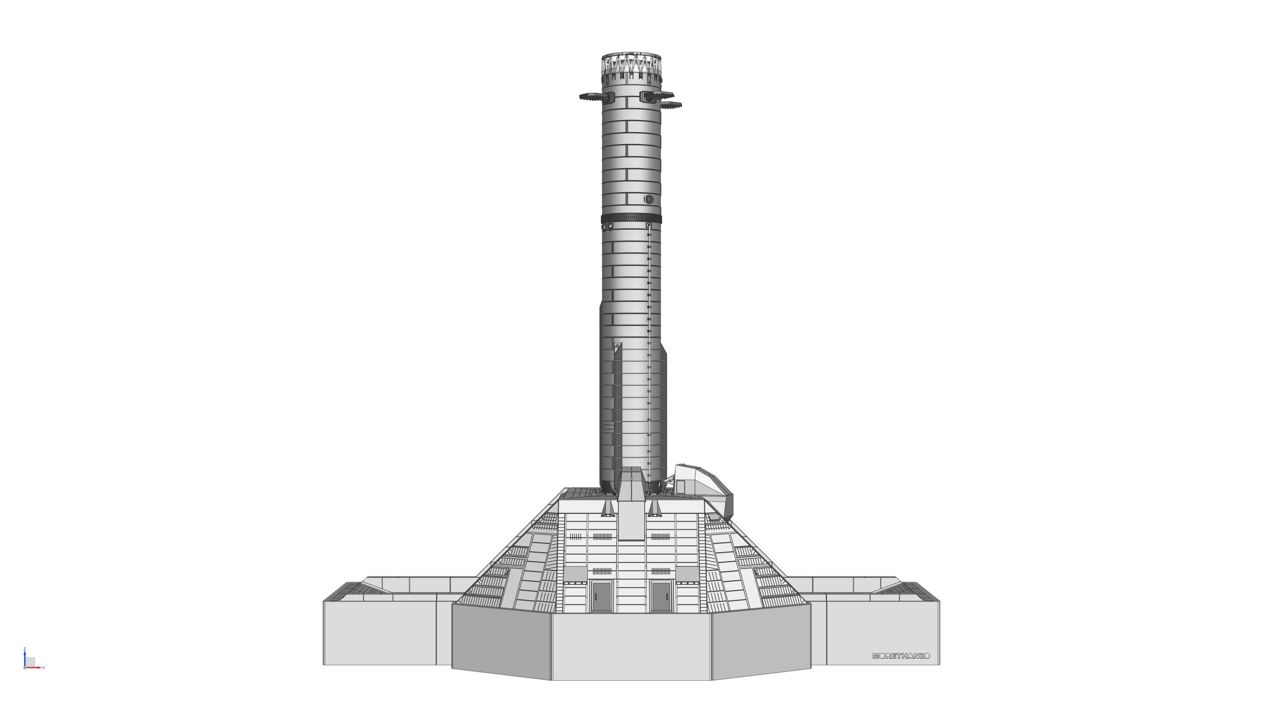
There is a STL file in folder ‘STEP 01’ called ‘Pad 2 Assembly’
If you load this file in your slicer, you’ll see the fully assembled PAD 2-S1 model. This will help you understand where each and every part is fitted on the model. -
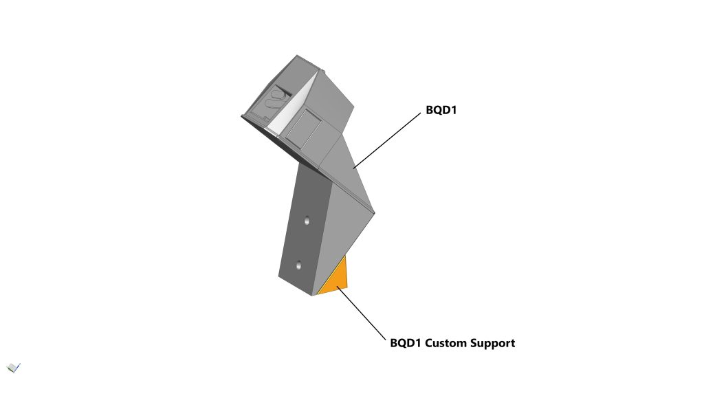
At STEP 14, the BQD1 and the BQD1 Custom Support must be loaded into the slicer and printed together. This sacrificial support increases the part’s stability during printing.
-
All magnet holes can be printed without support regardless of their positions/orientations on the model. Please don’t generate support for these holes (unless you really need to). Otherwise, you may struggle to remove support inside the holes due to restricted access.
-
This model is designed to allow you to assemble and disassemble the model into piece part level, because almost every part is held together by magnets. However, if you prefer to glue everything, or some parts, together, that’s also fine – but please be aware that if you do, it may be difficult to update the model later on.
-
This model is designed at 1:96 scale, hence, it is recommend that you print at this scale to achieve the highest quality. However, if you decide to print the model at a smaller scale, please be aware that the magnets we selected for this model will no longer fit and you will have to find smaller magnets to fit, or glue the parts together.
How to assemble the PAD 2-S1
So now you’ve got all your parts printed? Great! Let’s assemble the model!
I’ll take you through the assembly process step by step but before that, you need to purchase some items:
STEP 1: ‘Dry’ assemble the model
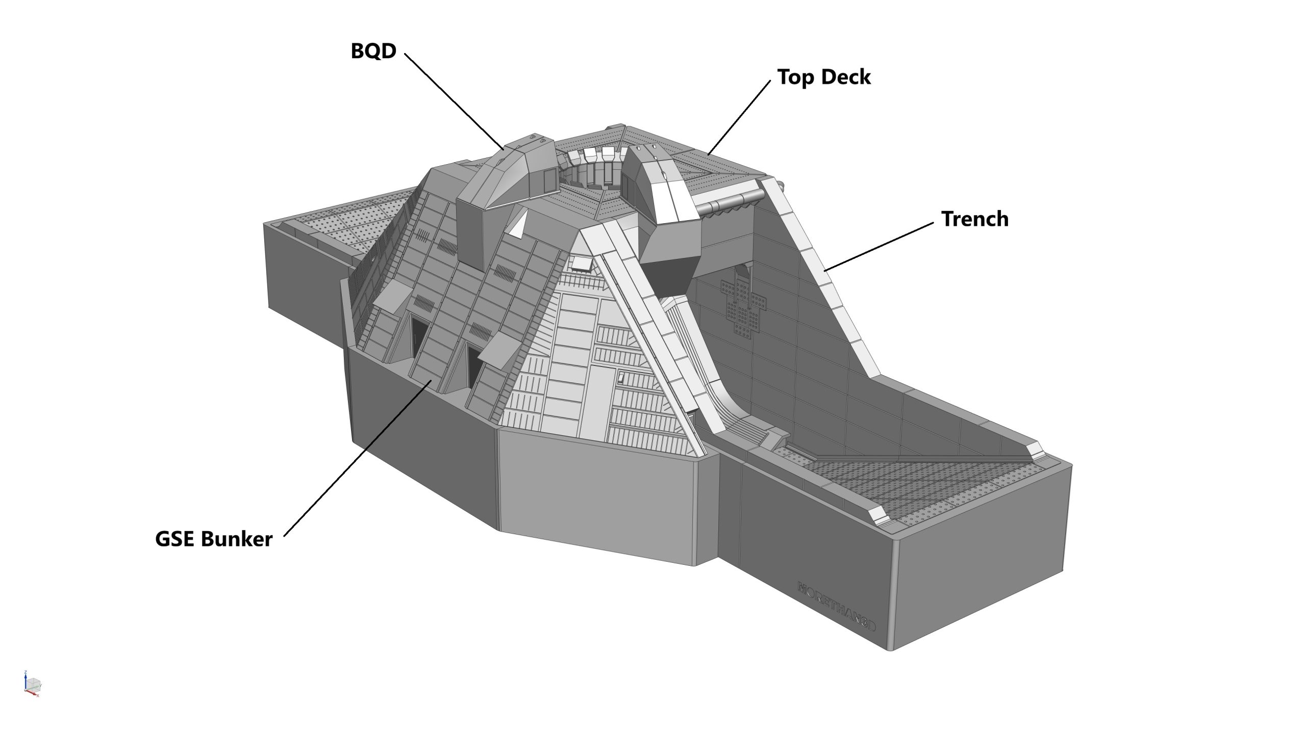
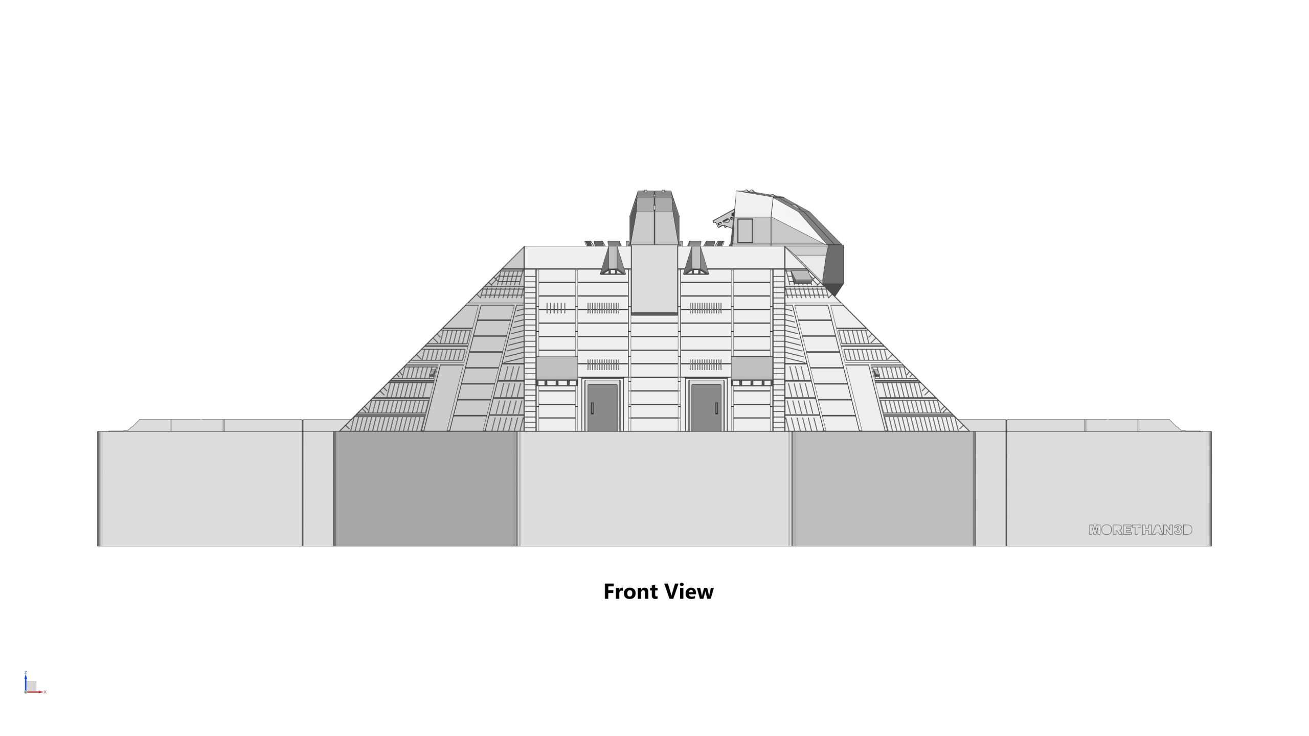
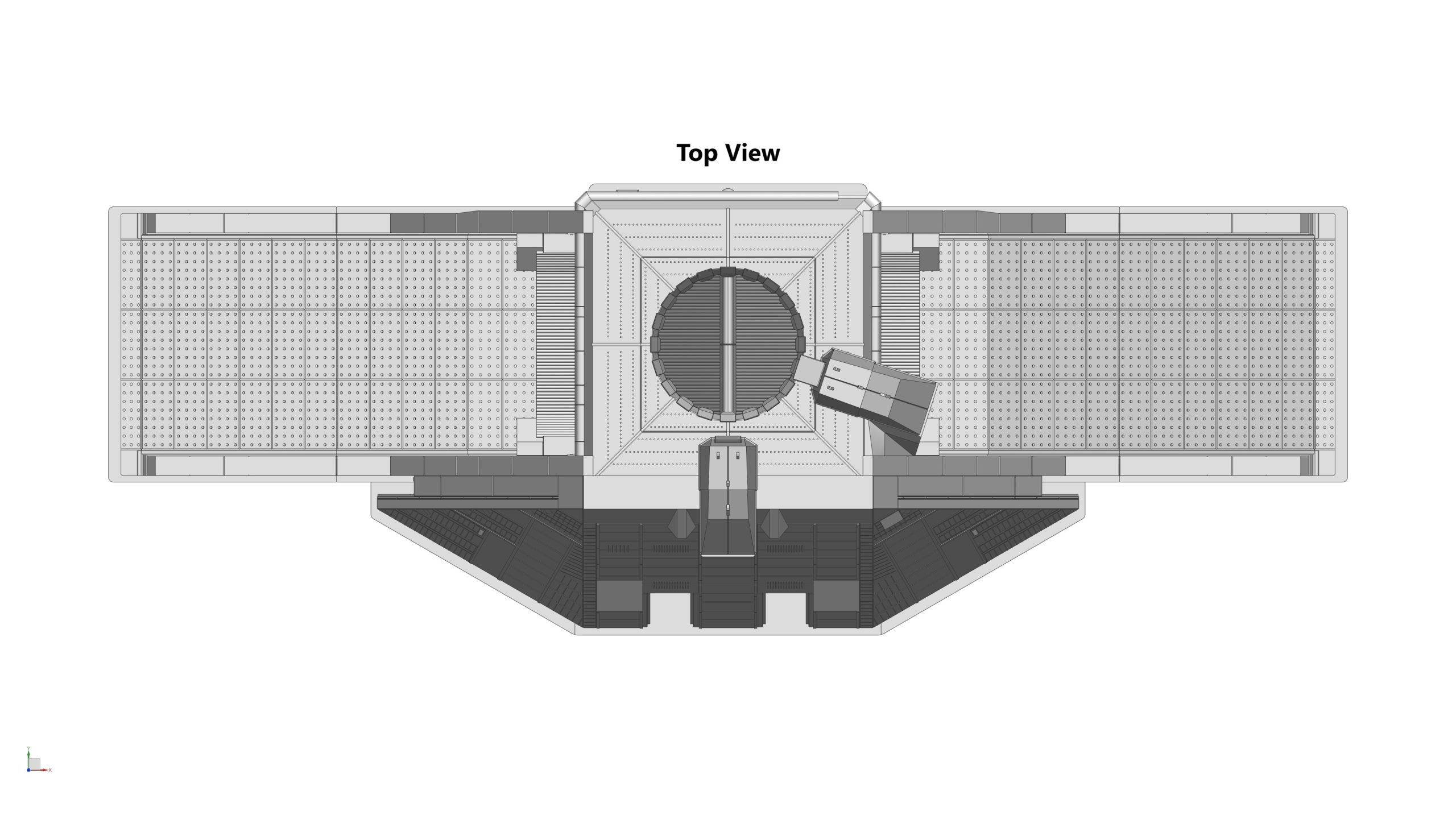
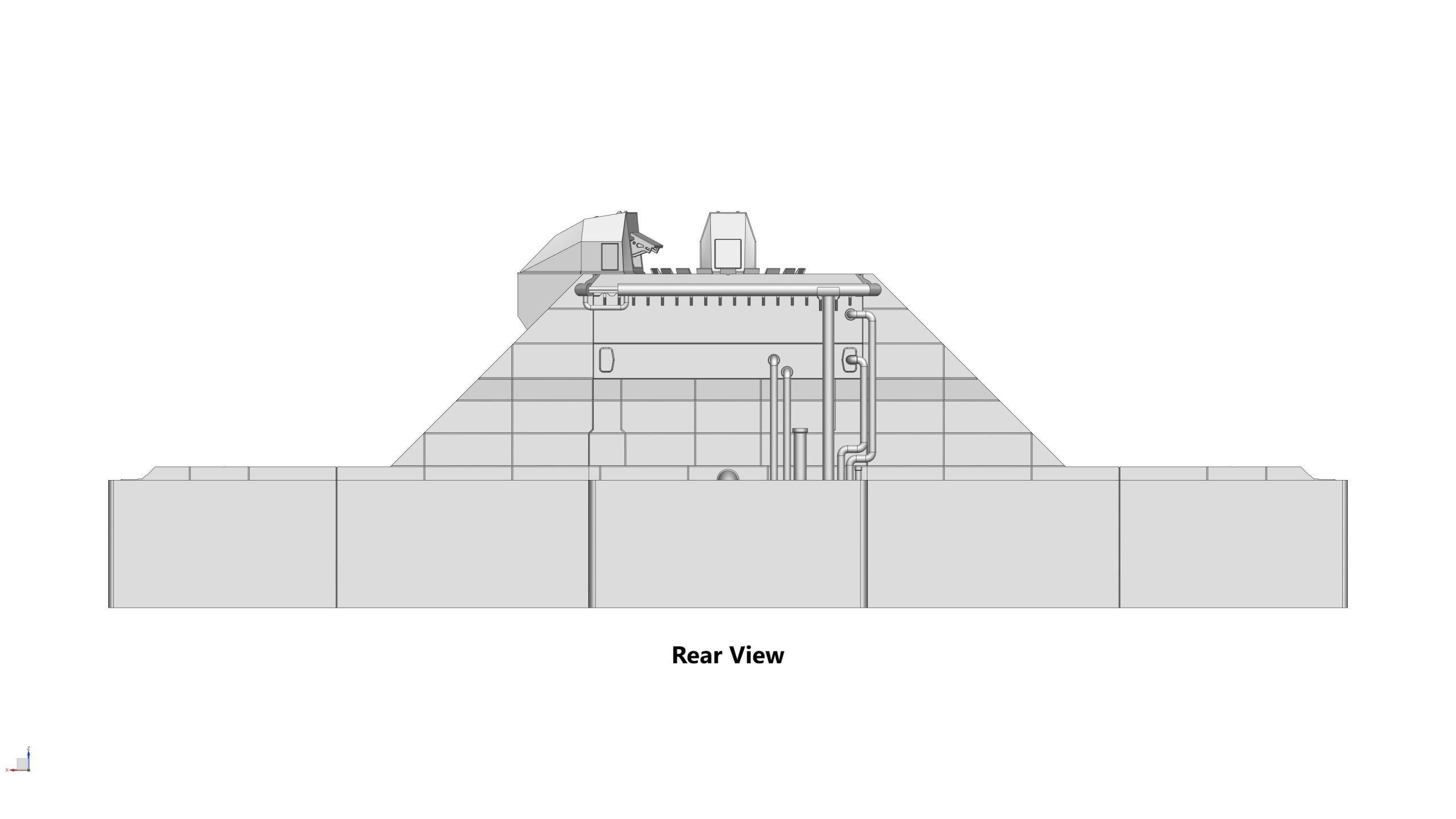
At this step, all I want you to do is try to stack all the parts together to get a good understanding of where they are located. Because there are a lot of magnets you need to fit during the assembly process, doing this first step will give you an idea of how to fit the magnets in each part correctly. Please use the files in STEP 01 folder, and the photos below if required.
STEP 2: Assemble the Flame Diverter
Parts required (refer to the photos below)
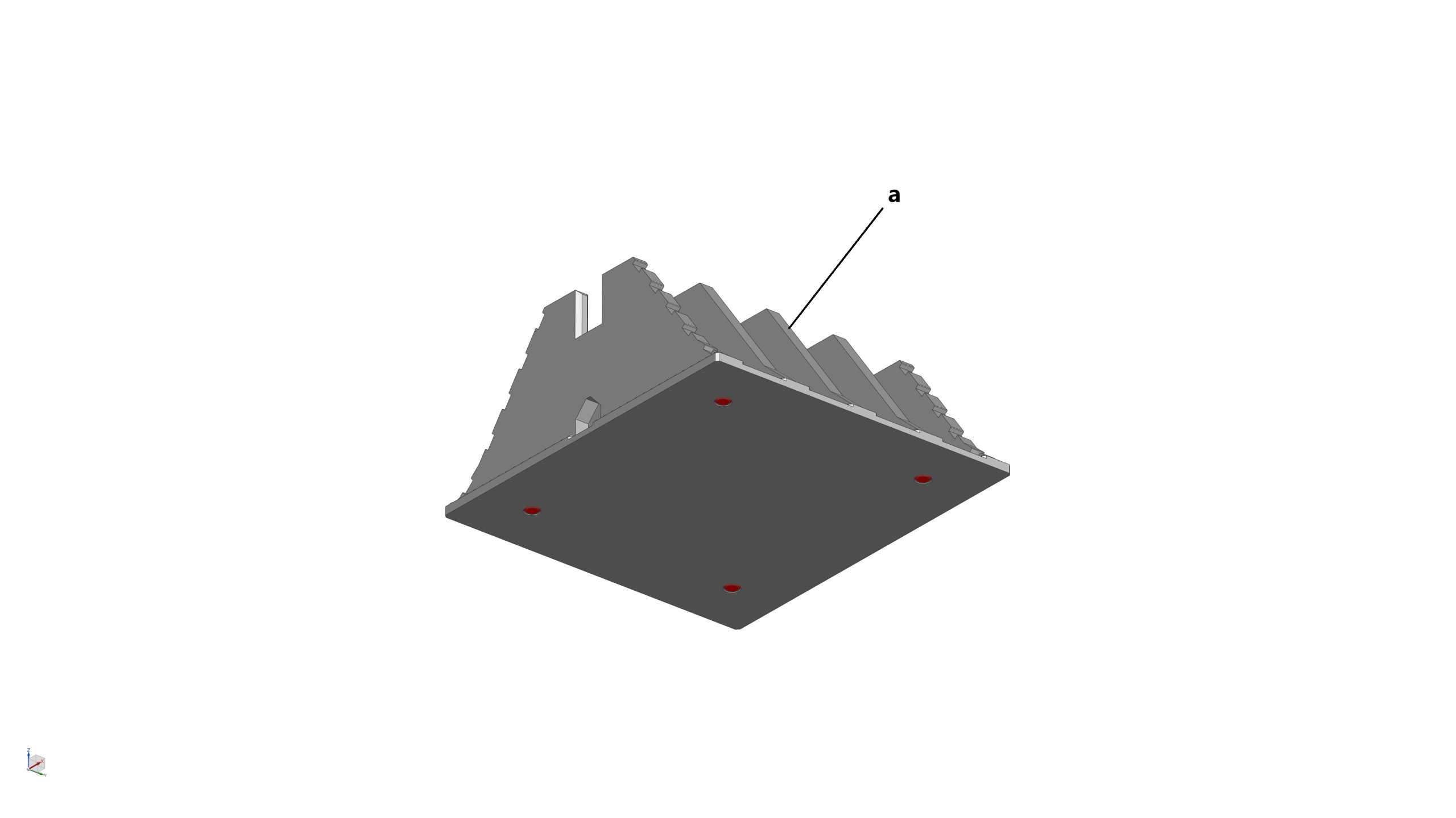
- 1x Diverter Support Base (a)
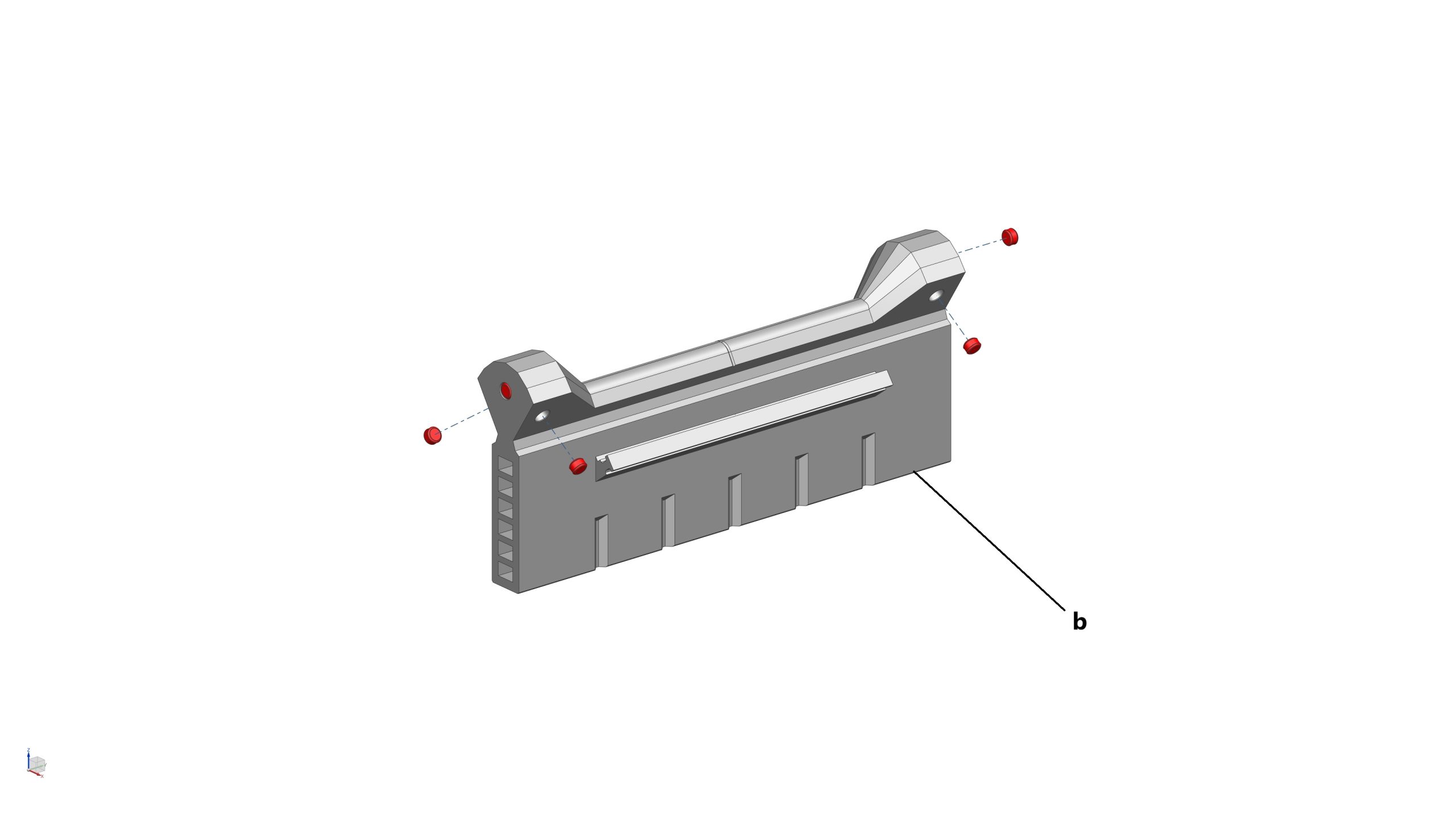
- 1x Diverter Support Cross Channel (b)
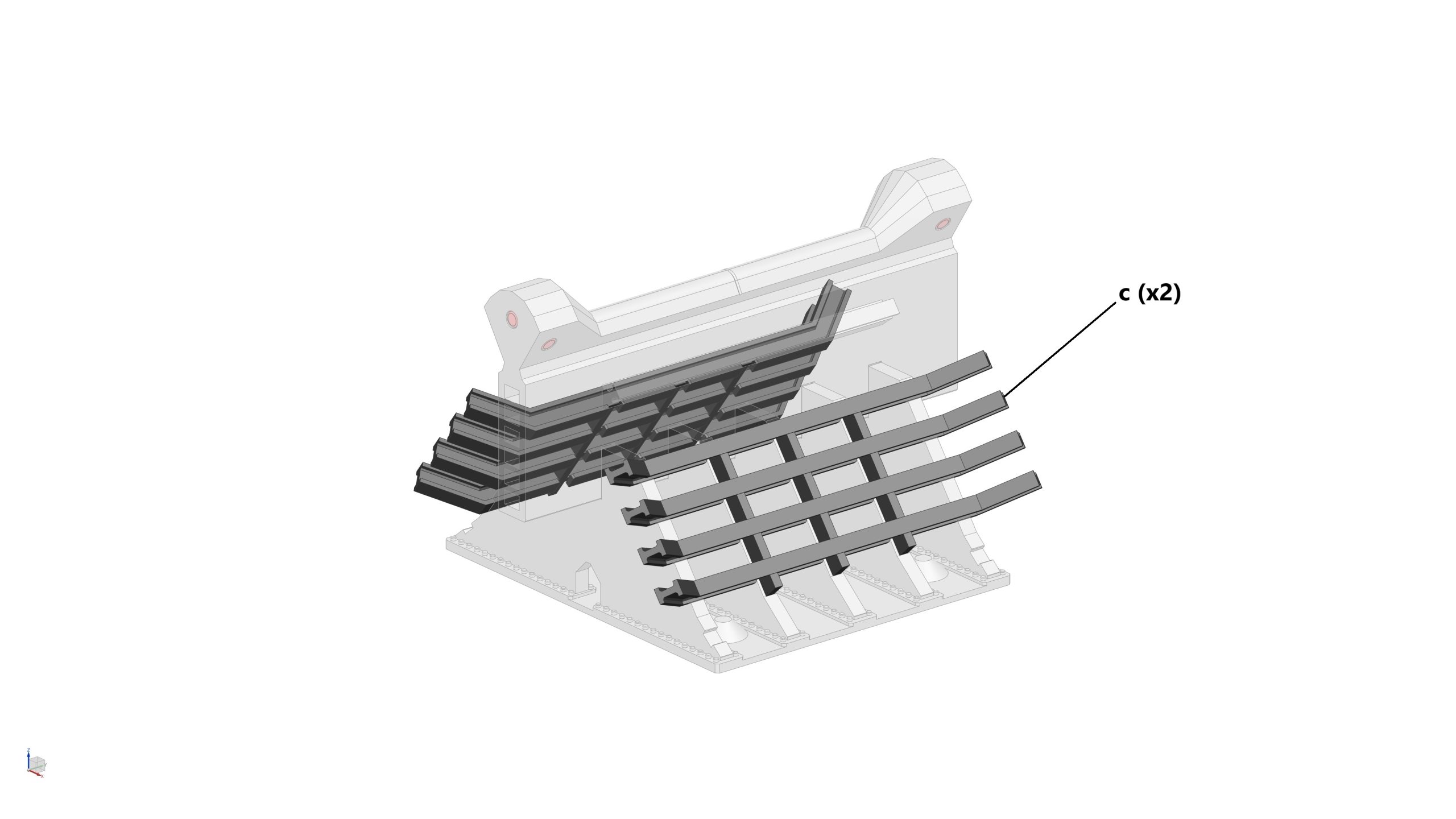
- 2x Diverter Support I Beams_01 (c)
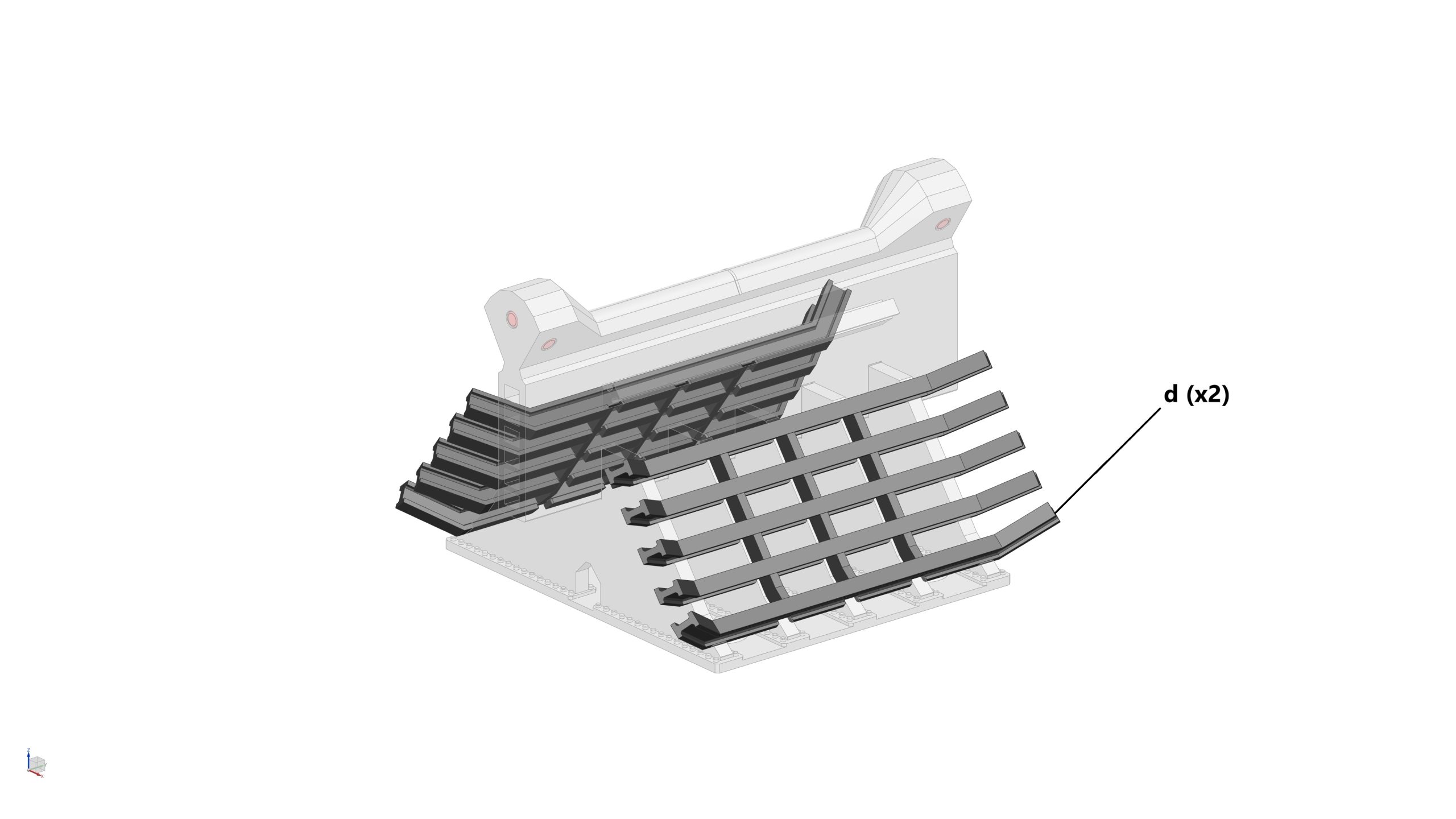
- 2x Diverter Support I Beams_02 (d)
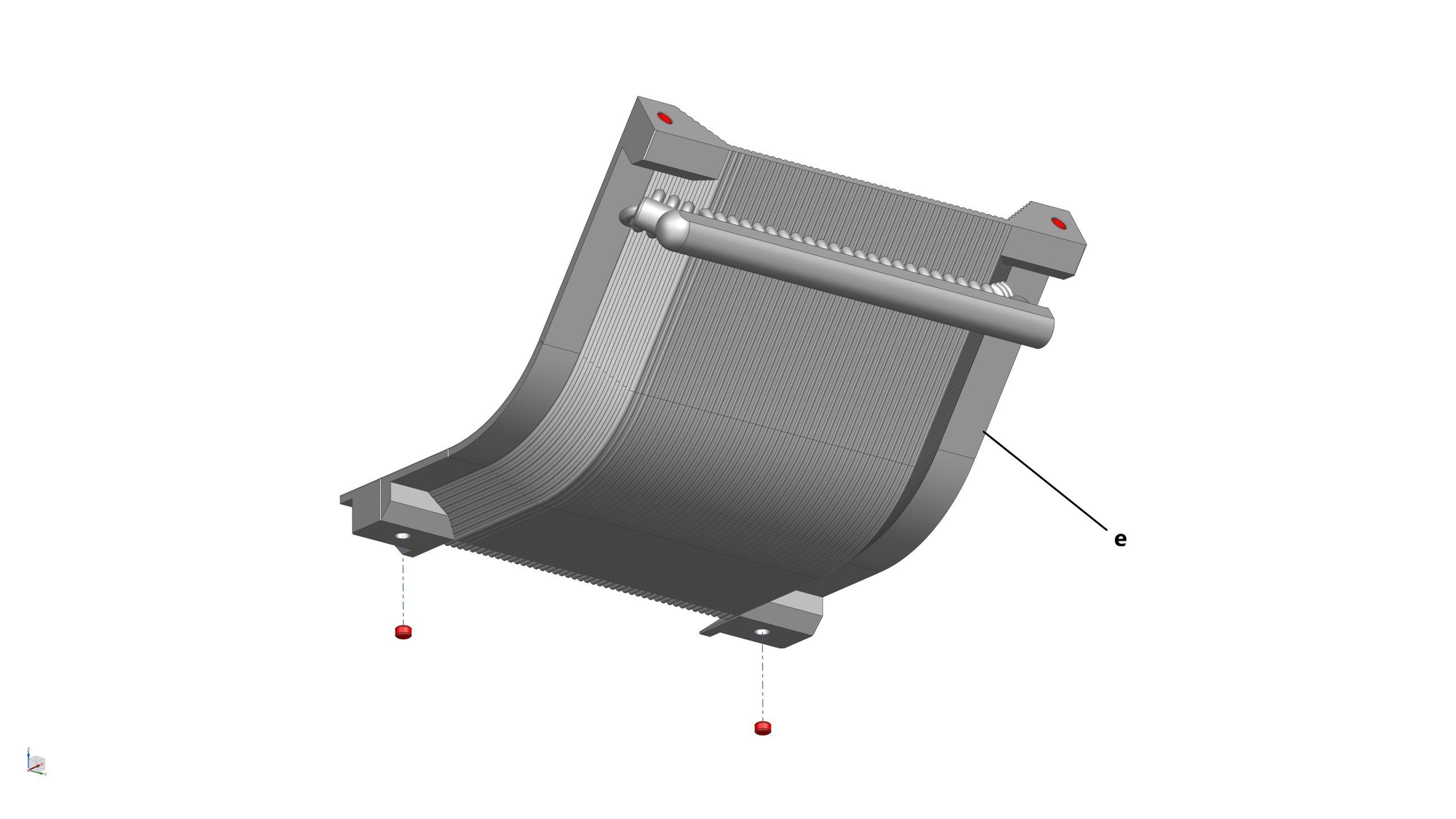
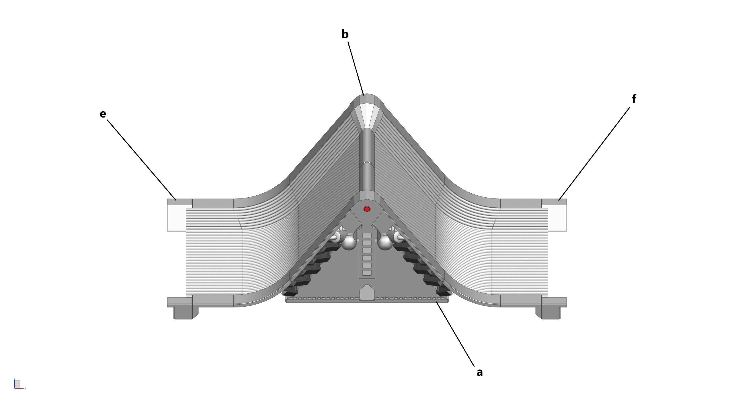
- 1x Trench Deluge Pipes (LH)_S1 (e)
- 1x Trench Deluge Pipes (RH)_S1 (f)
- 18x Magnets (5mm dia x 3mm thick) (highlighted in red)
Assembly process
- STEP 2a: Glue 4x magnets (5mm dia x 3mm thick) into their pockets at the bottom face of the Diverter Support Base
- STEP 2b: Glue 6x magnets (5mm dia x 3mm thick) into their pockets near the top of the Diverter Support Cross Channel
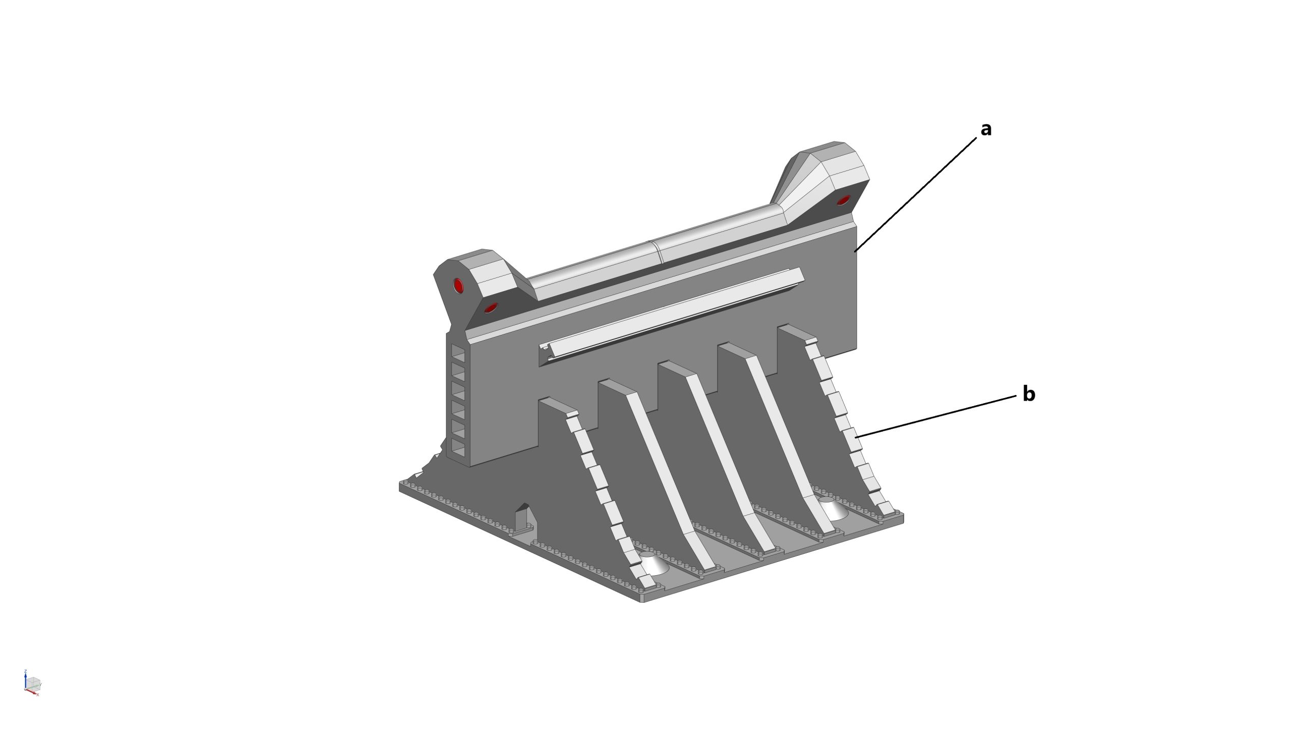
- STEP 2c: Glue the Diverter Support Cross Channel to the Diverter Support Base
- STEP 2d: Glue 2x Diverter Support I Beams_01 to each side of the Diverter Support Base
- STEP 2e: Glue 2x Diverter Support I Beams_02 to each side of the Diverter Support Base
- STEP 2f: Glue 4x magnets (5mm dia x 3mm thick) into their pockets at the corners of the Trench Deluge Pipes (LH), and Trench Deluge Pipes (RH)
- STEP 2g: Install the Trench Deluge Pipes (LH) & (RH) to the Diverter Support
STEP 3: Assemble The Trench - Block 1
Parts required (refer to the photos below)
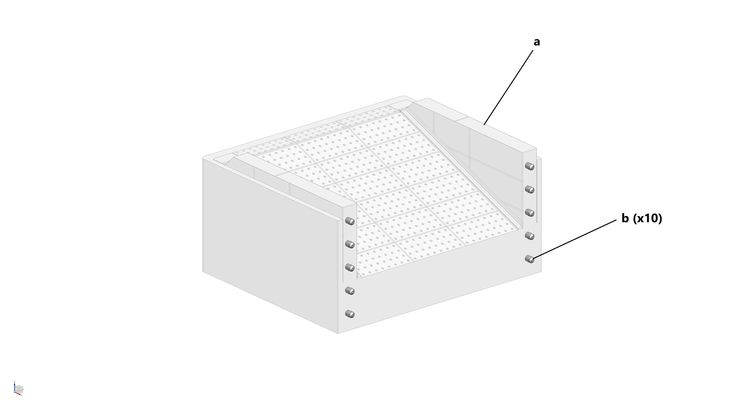
- 1x Block 1 (a)
- 10x Locating Pin (b)
Assembly process:
- STEP 3a: Insert 10x locating pins to the side wall of Block 1
STEP 4: Assemble The Trench - Block 2
Parts required (refer to the photos below)
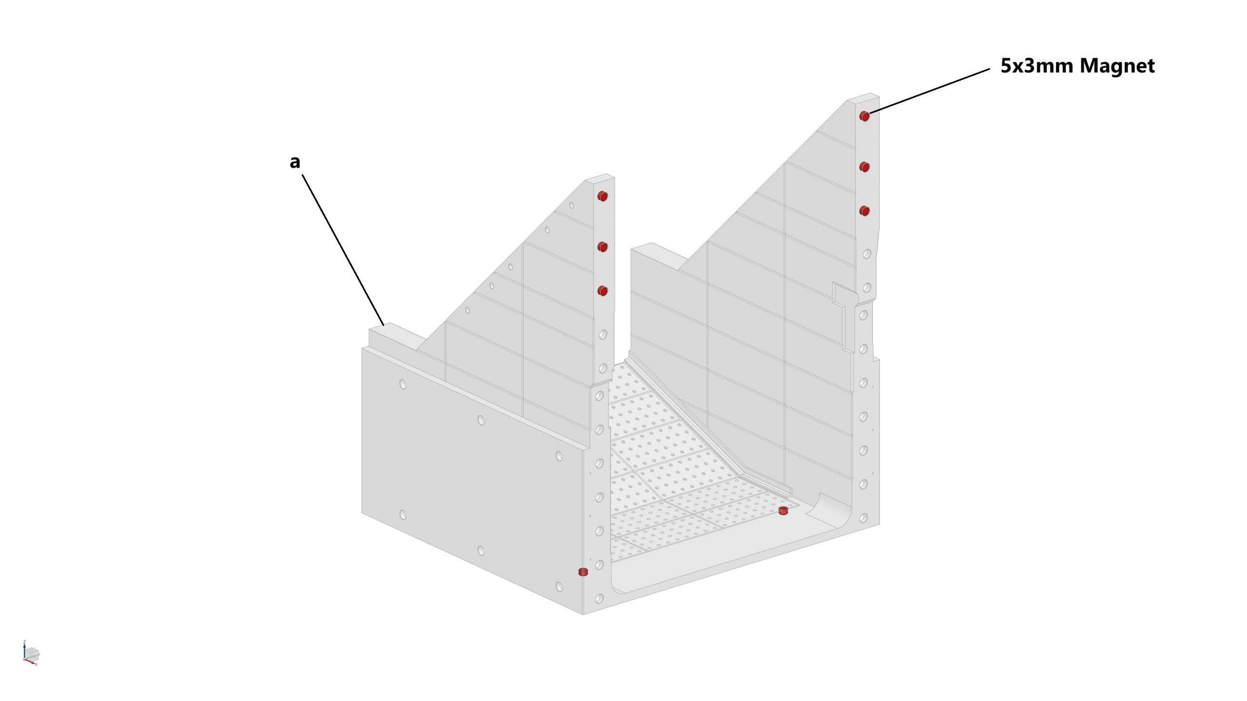
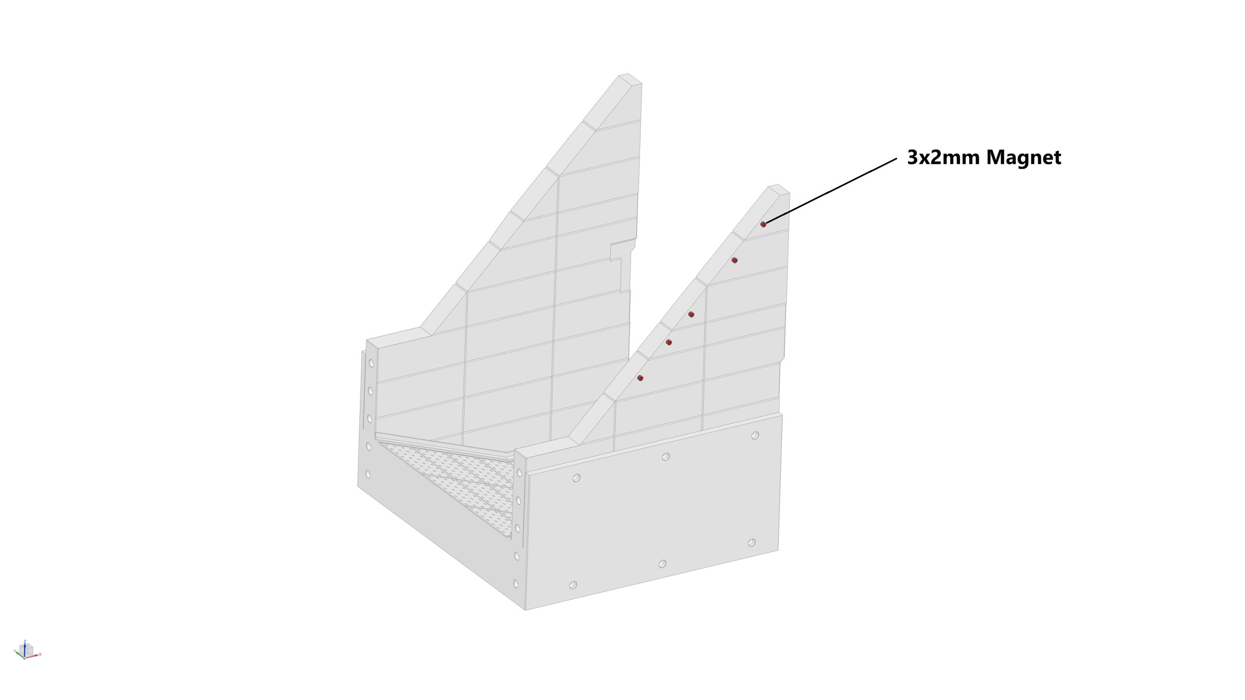
- 1x Block 2 (a)
- 5x Magnets (3mm dia x 2mm thick) (highlighted in red)
- 8x Magnets (5mm dia x 3mm thick) (highlighted in red)
Assembly process
- STEP 4a: Glue 8x magnets (5mm dia x 3mm thick) into their pockets near the top of the side wall (x6), and at the bottom (x2) wall of Block 2
- STEP 4b: Glue 5x magnets (3mm dia x 2mm thick) into their pockets at the front wall of Block 2
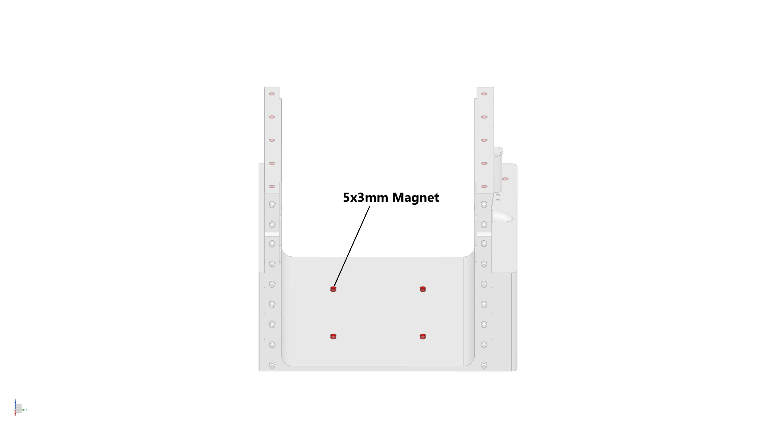
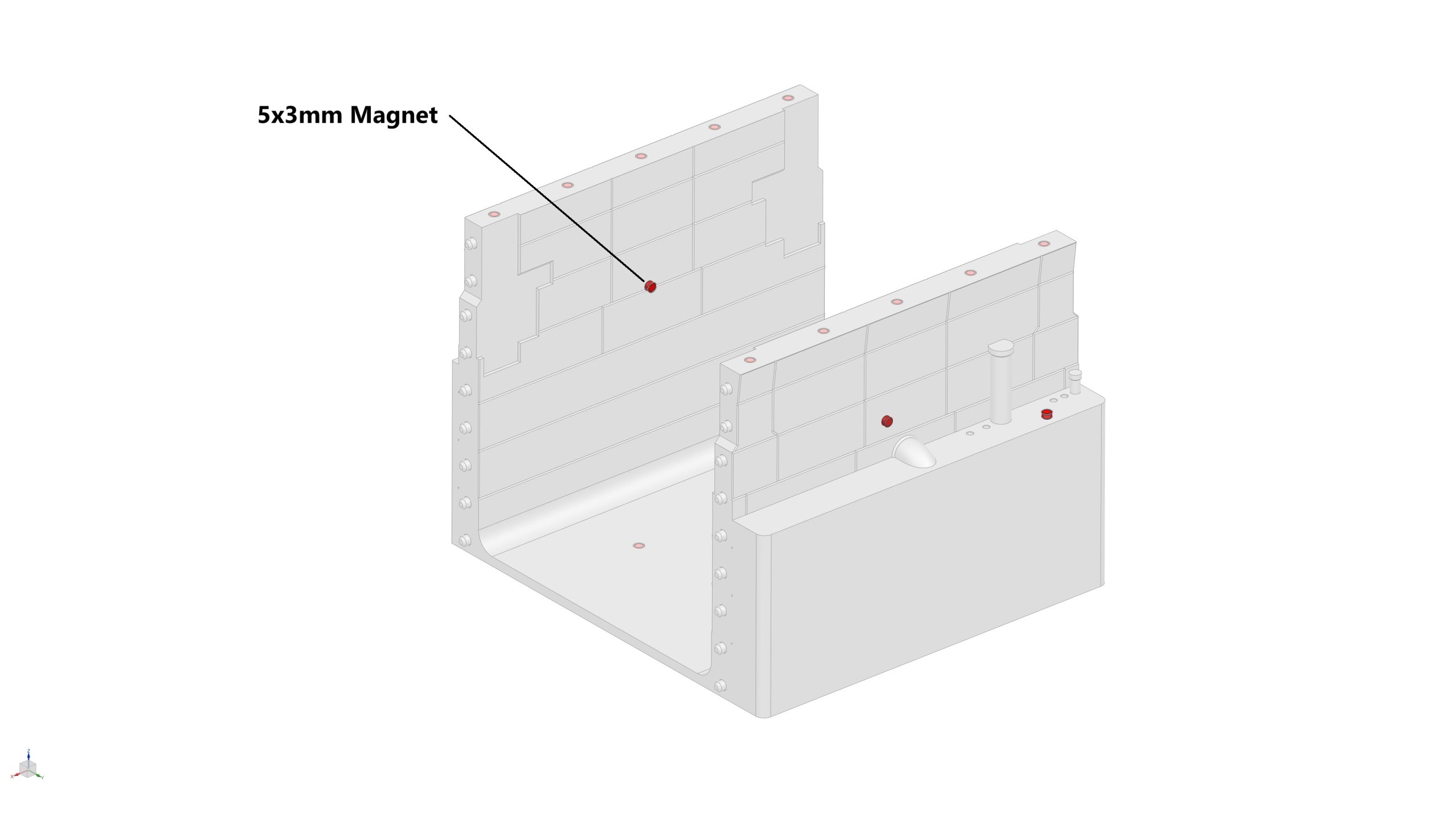
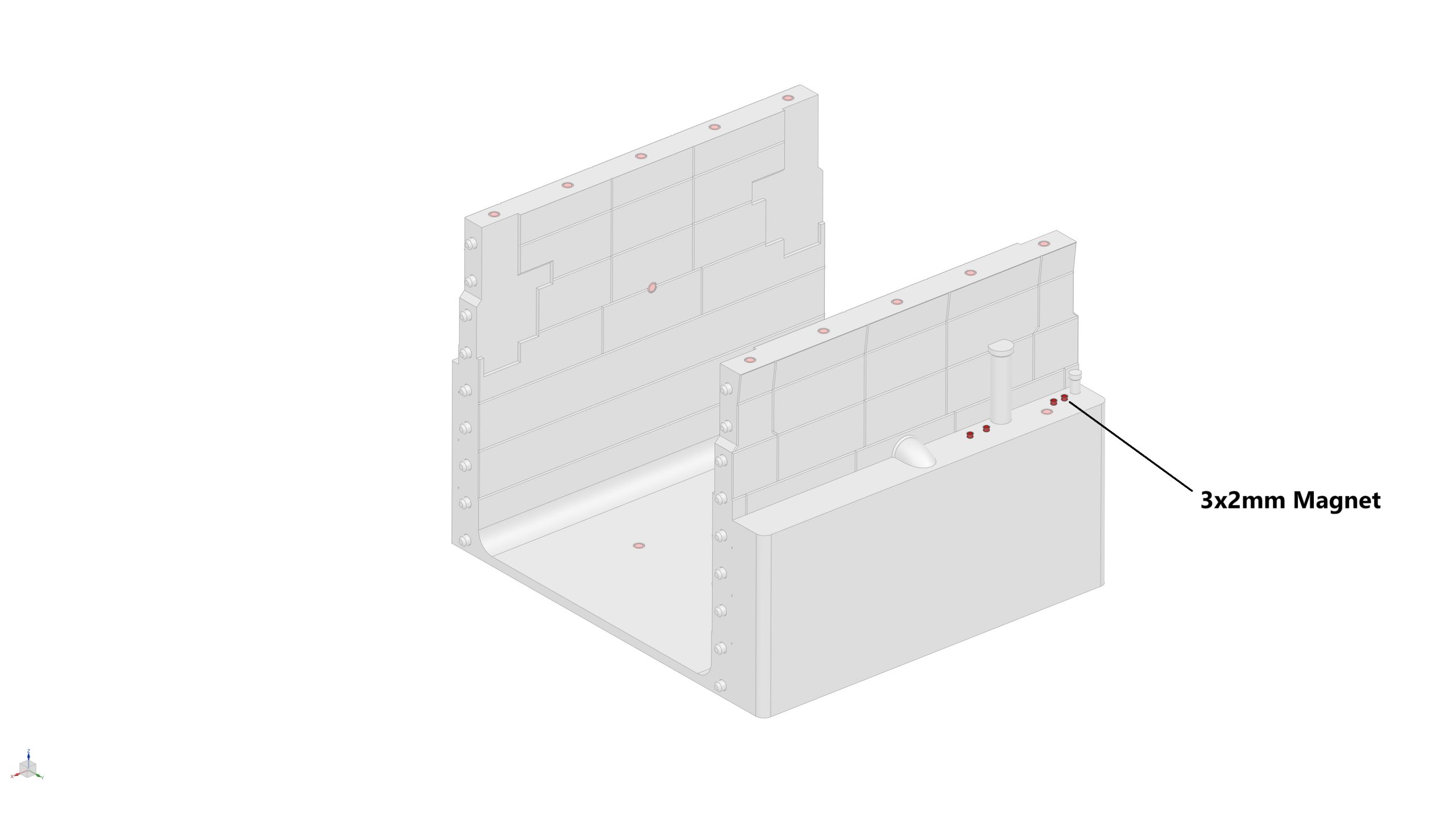
STEP 5: Assemble The Trench - Block 3
Parts required (refer to the photos below)
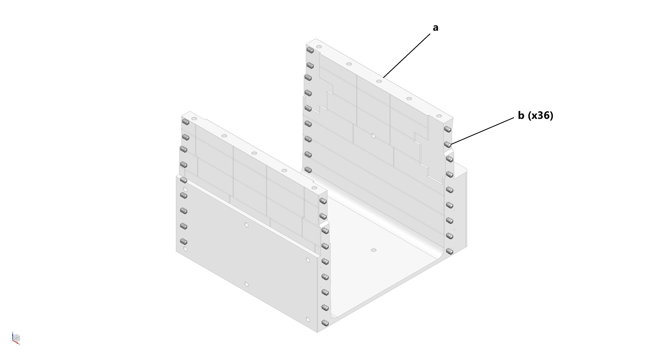
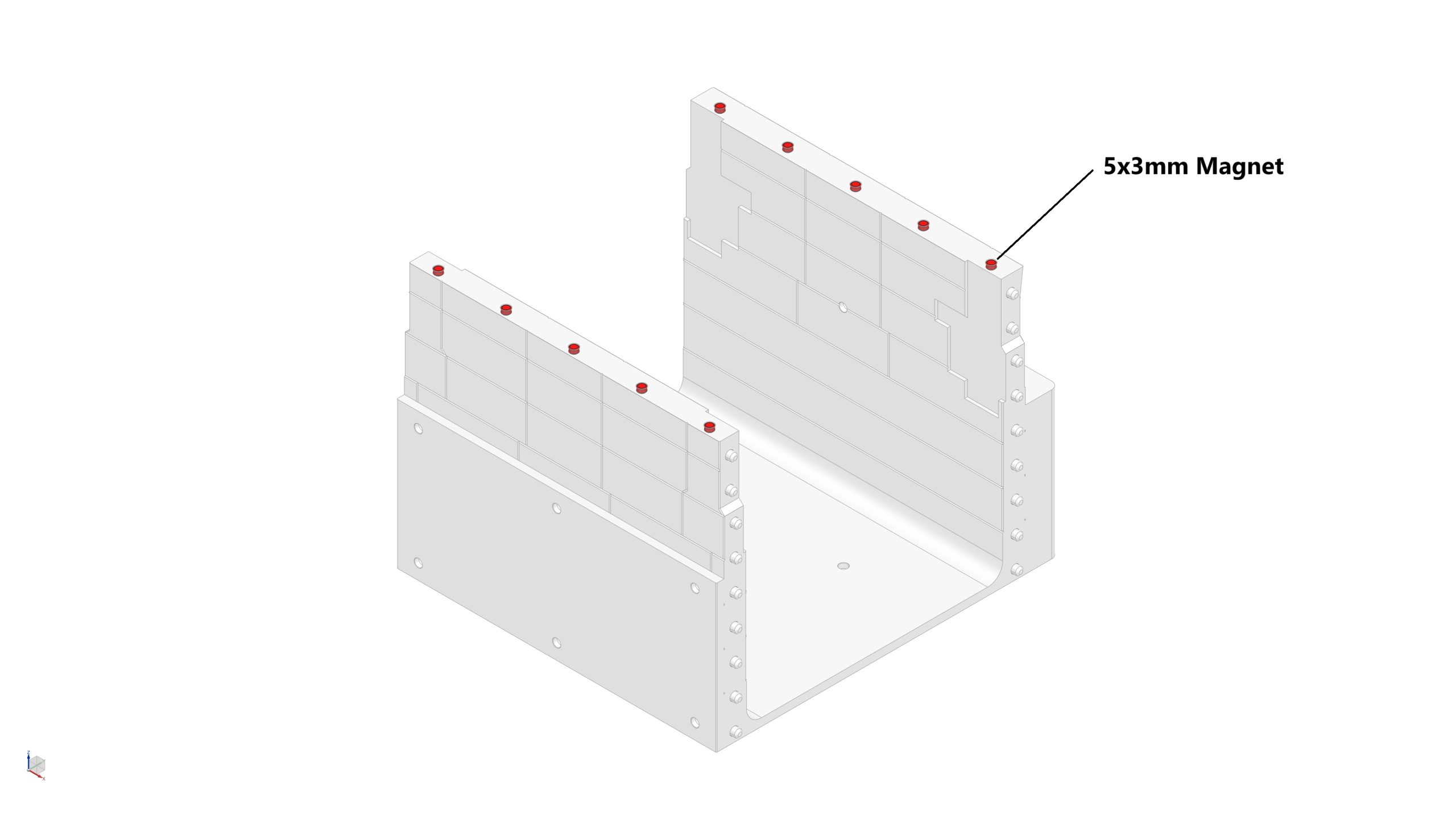
- 1x Block 3 (a)
- 36x Locating Pin (b)
- 4x Magnets (3mm dia x 2mm thick) (highlighted in red)
- 17x Magnets (5mm dia x 3mm thick) (highlighted in red)
Assembly process
- STEP 5a: Insert 36x locating pins to both right and left side wall of Block 3
- STEP 5b: Glue 10x magnets (5mm dia x 3mm thick) into their pockets at the top side of Block 3
- STEP 5c: Glue 4x magnets (5mm dia x 3mm thick) into their pockets at the bottom wall of Block 3
- STEP 5d: Glue 3x magnets (5mm dia x 3mm thick) into their pockets at the inner walls (x2), and near the plumbing behind the rear wall (x1) of Block 3
- STEP 5e: Glue 4x magnets (3mm dia x 2mm thick) into their pockets near the plumbing behind the rear wall of Block 3
STEP 6: Assemble The Trench - Block 4
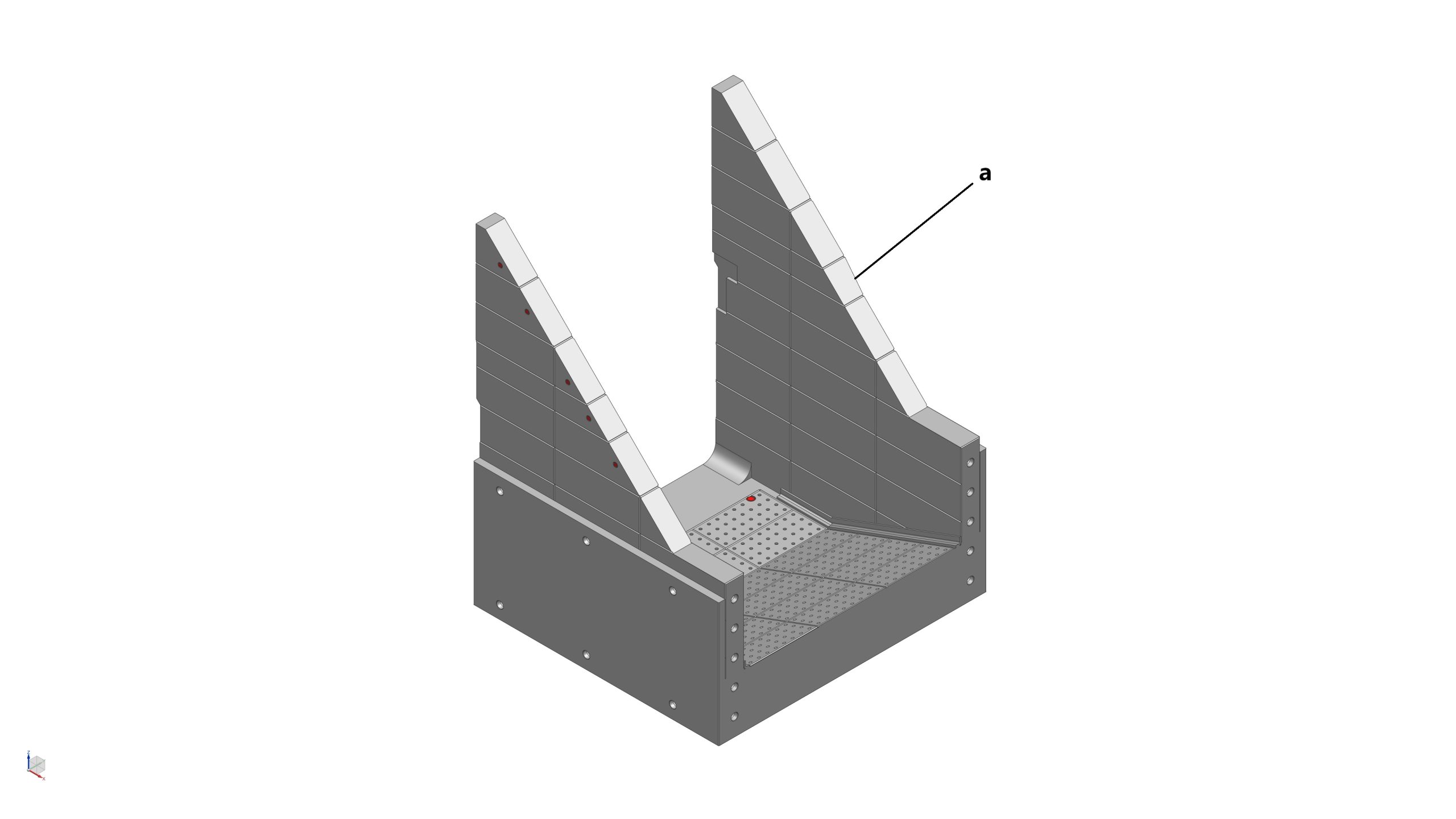
Parts required (refer to the photos below)
- 1x Block 4 (a)
- 5x Magnets (3mm dia x 2mm thick) (highlighted in red)
- 8x Magnets (5mm dia x 3mm thick) (highlighted in red)
Assembly process
- STEP 6: Very similar to Block 2 – glue 8x magnets (5mm dia x 3mm thick) into their pockets near the top of the side wall (x6), and at the bottom (x2) wall of Block 4, then glue 5x magnets (3mm dia x 2mm thick) into their pockets at the front wall of Block 4
STEP 7: Assemble The Trench - Block 5
Parts required (refer to the photos below)
- 1x Block 1 (a)
- 10x Locating Pin (b)
Assembly process
- STEP 7: Very similar to Block 1 – insert 10x locating pins to the side wall of Block 1
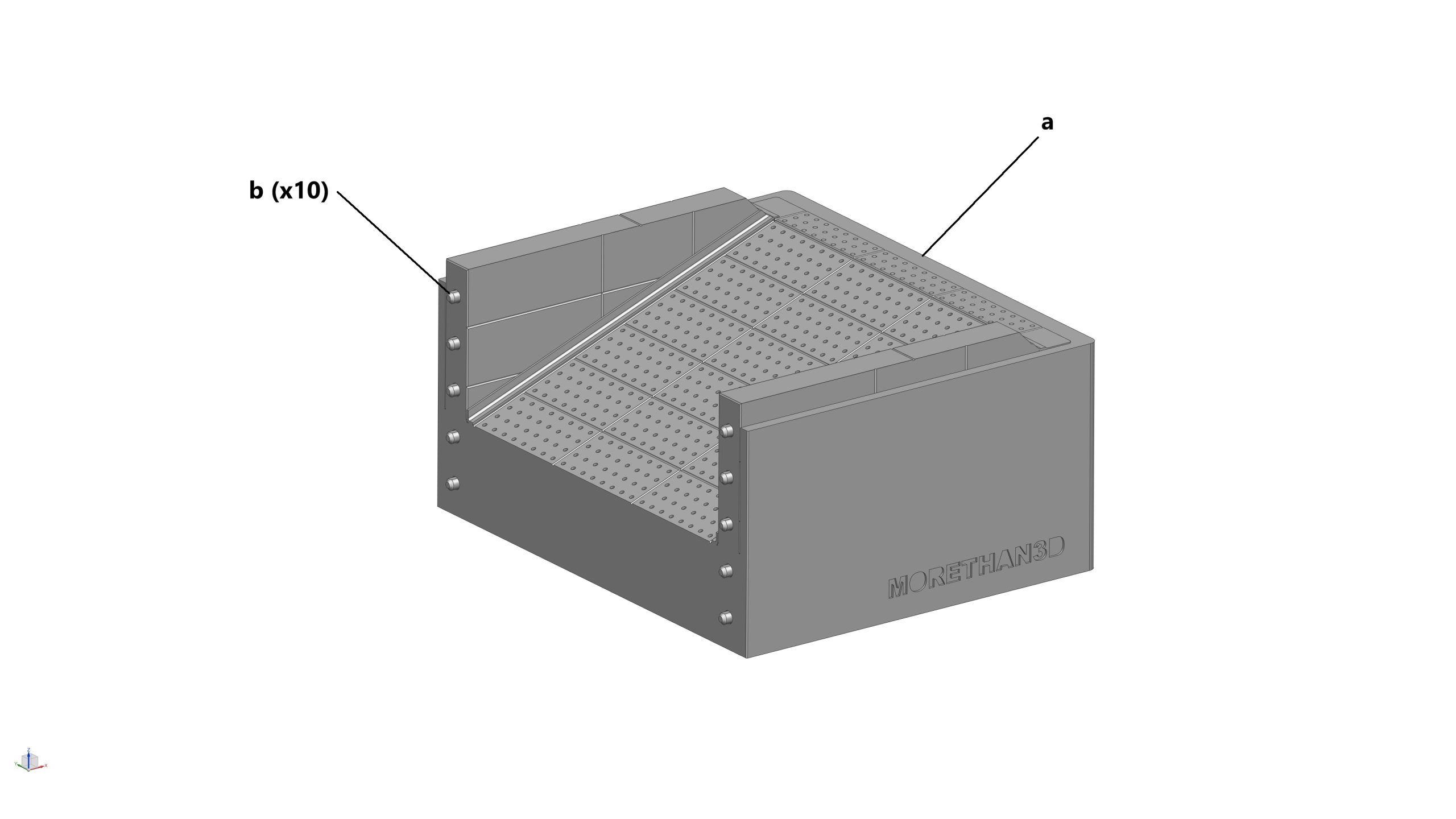
STEP 8: Assemble the Trench
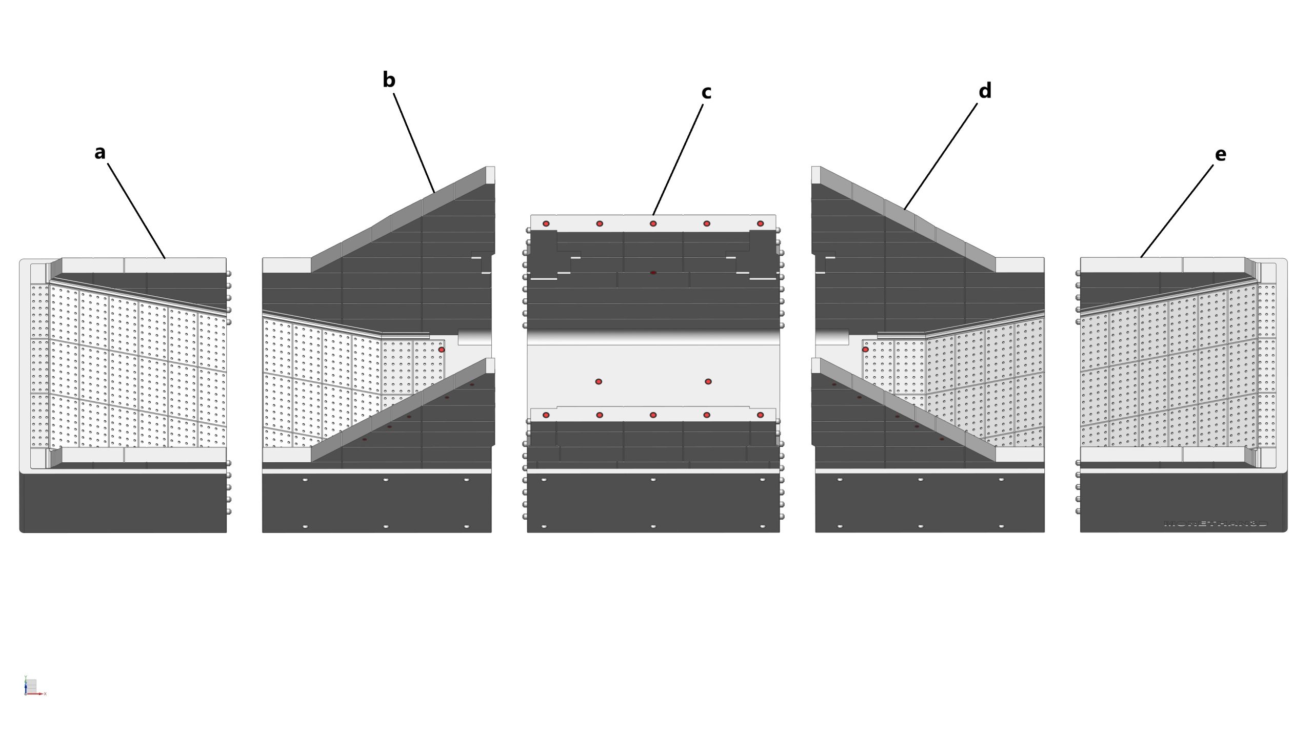
Parts required (refer to the photos below)
- 1x Block 1 from STEP 3 (a)
- 1x Block 2 from STEP 4 (b)
- 1x Block 3 from STEP 5 (c)
- 1x Block 4 from STEP 6 (d)
- 1x Block 5 from STEP 7 (e)
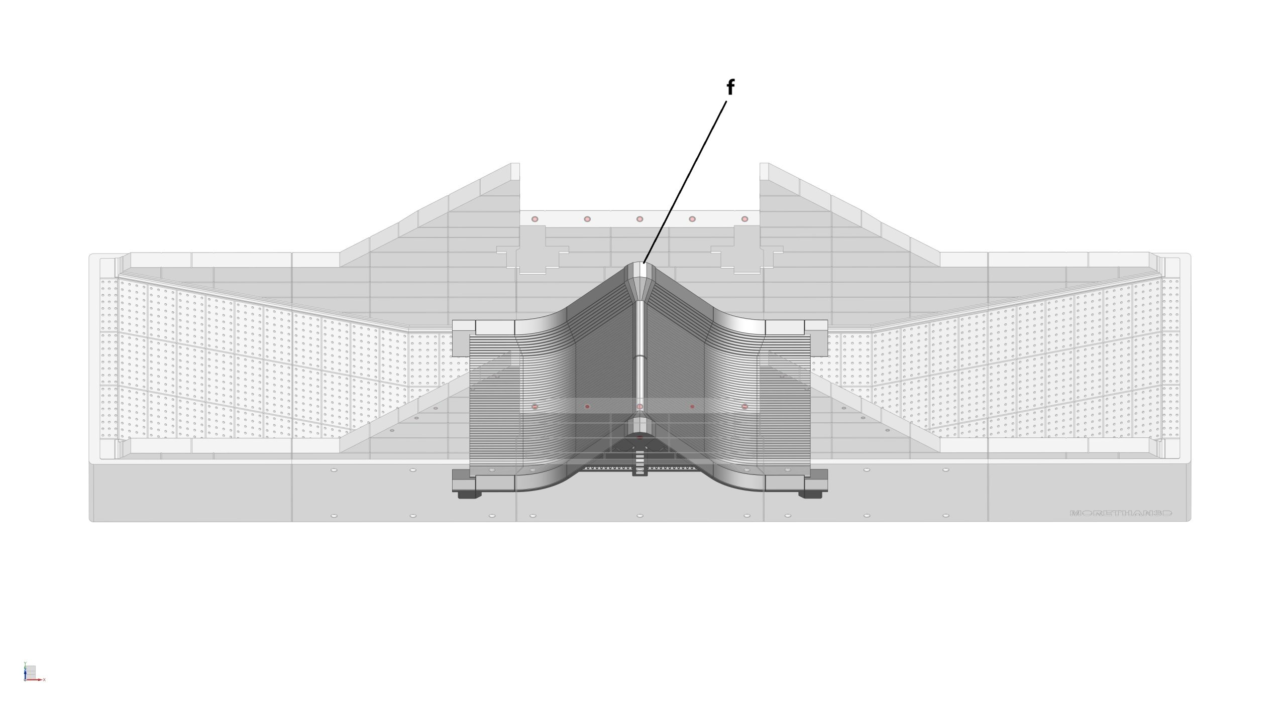
- 1x Flame Diverter from STEP 2 (f)
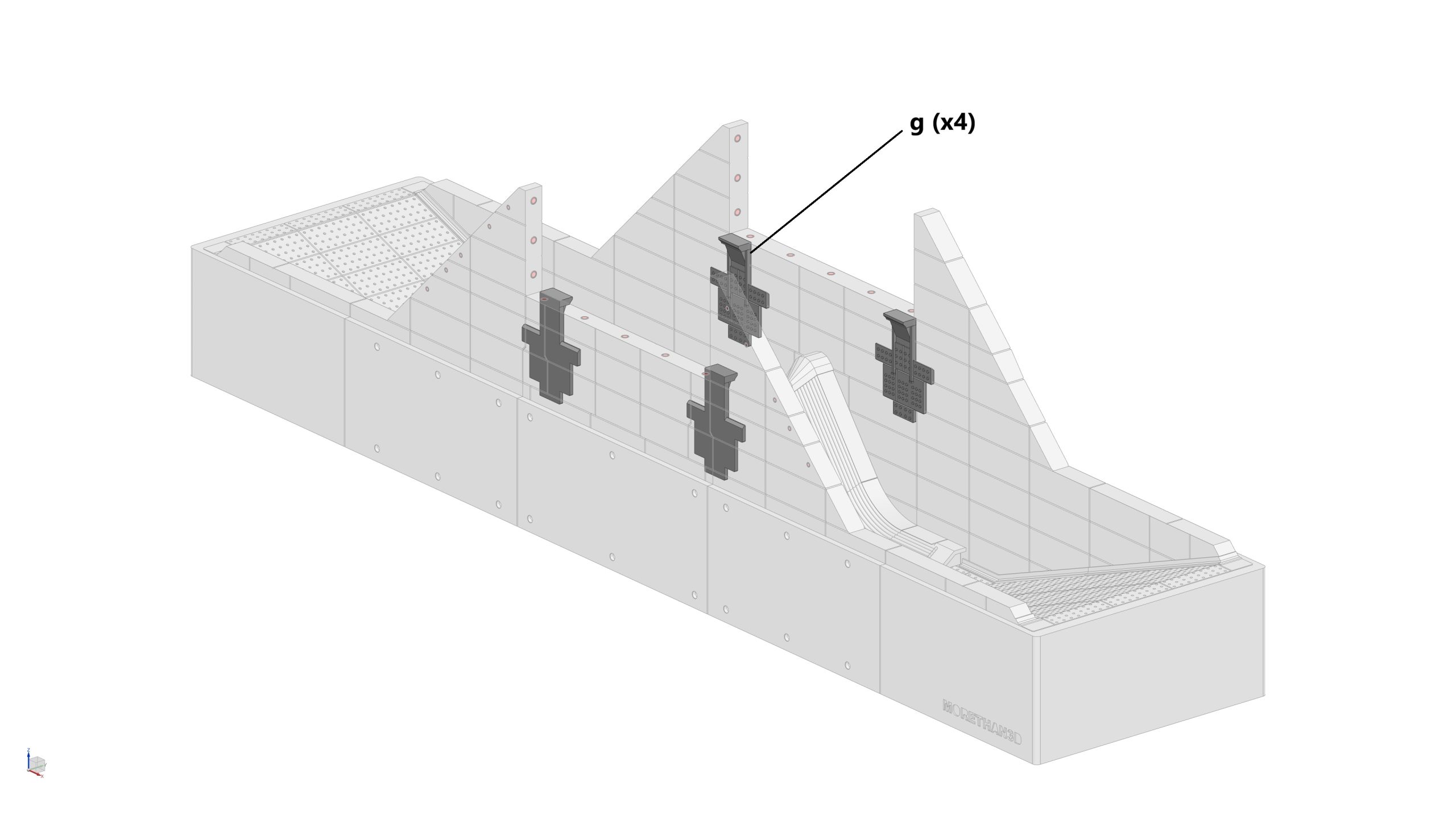
- 4x Shielding Plates (g)
Assembly process
- STEP 8a: Assemble all 5 blocks together
- STEP 8b: Install the Flame Diverter into the Trench
- STEP 8c: Glue 4x Shielding Plates into their locations on the inner walls of the Trench
STEP 9: Assemble the Clamping System
Parts required (refer to the photos below)
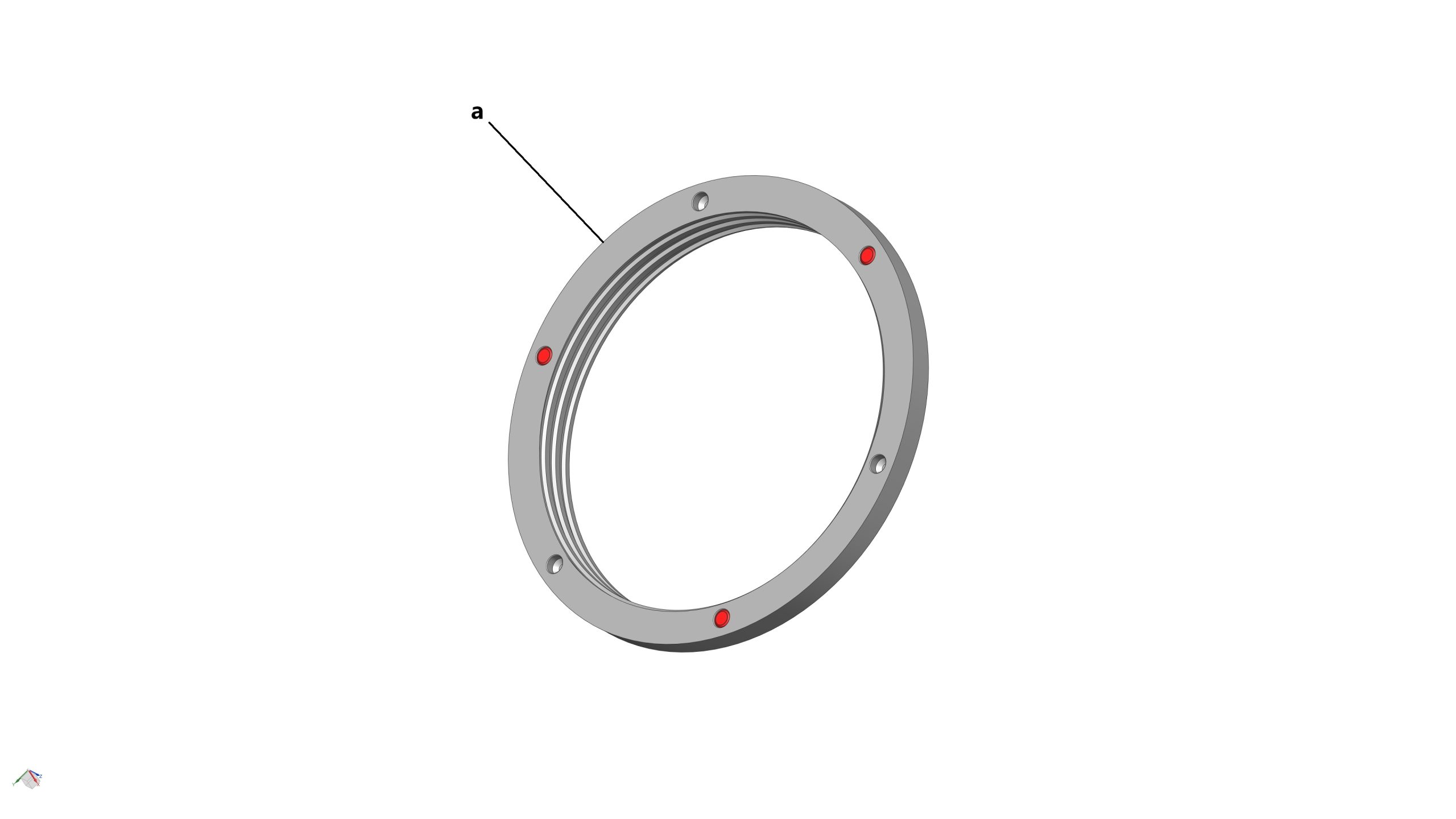
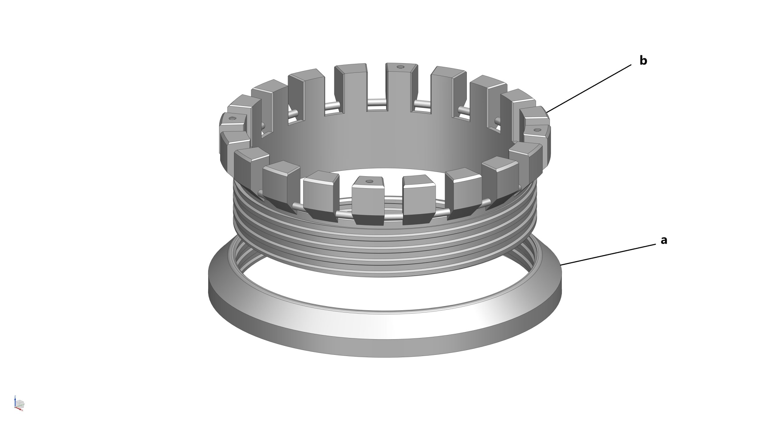
- 1x Threaded Ring (a)
- 1x Inner Ring (b)
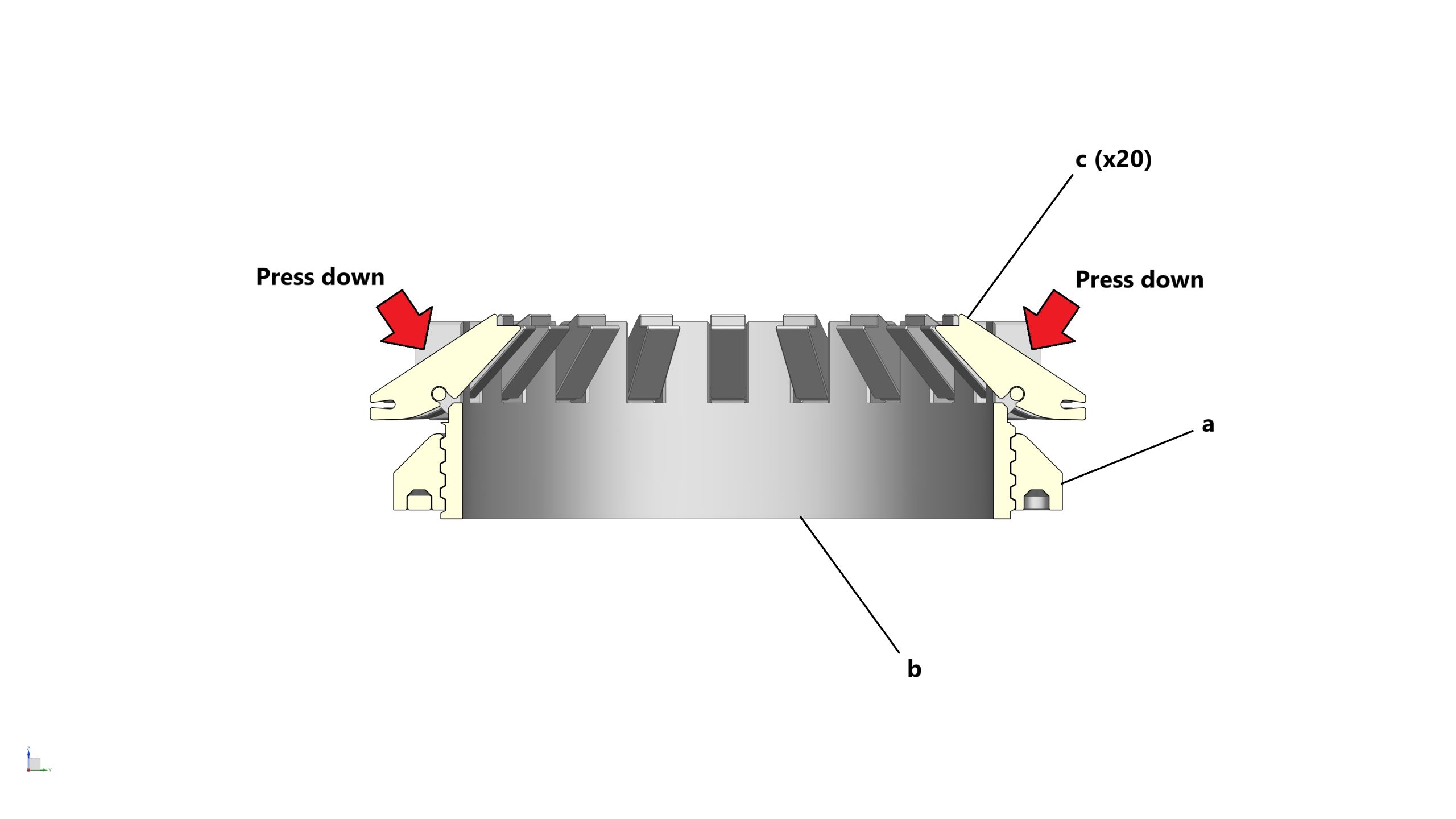
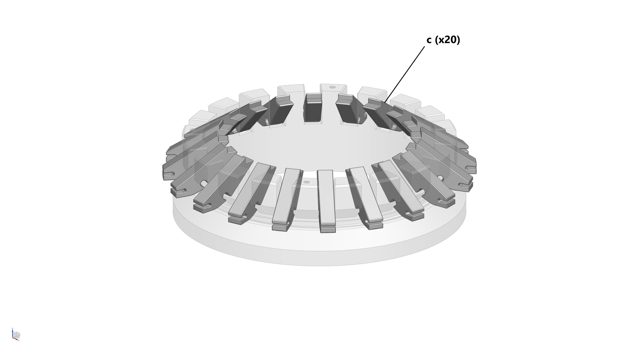
- 20x Fingers (a.k.a. Booster hold down clamps) (c)
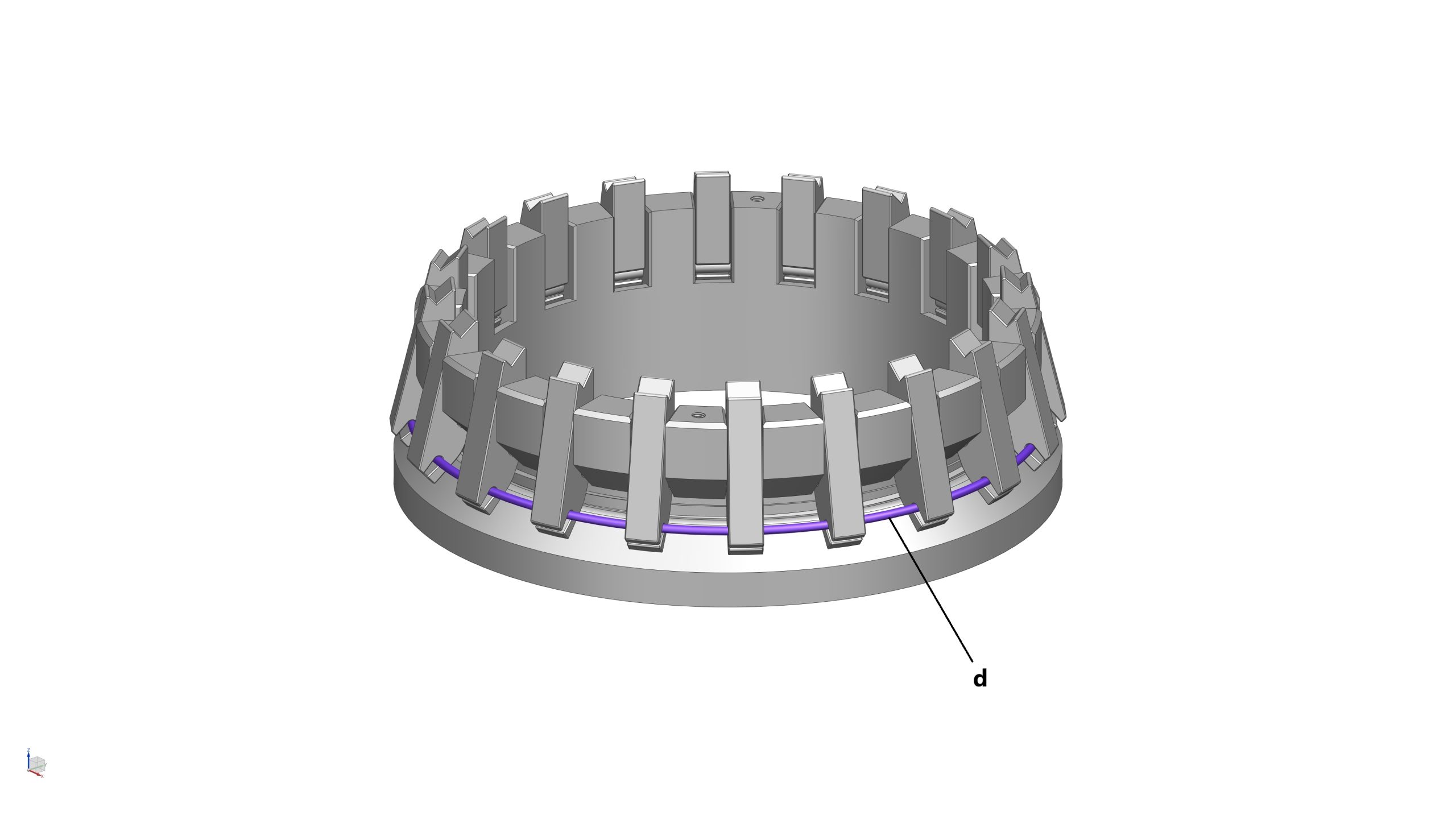
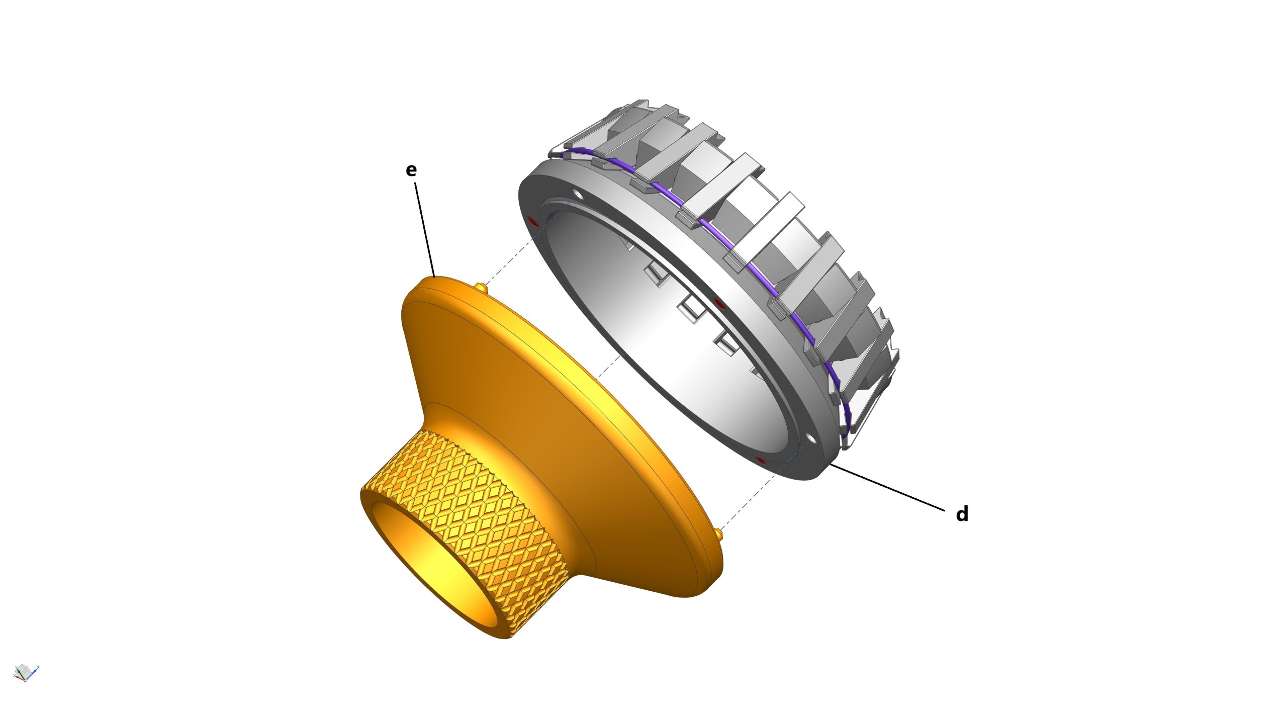
- 1x Elastic Band (d)
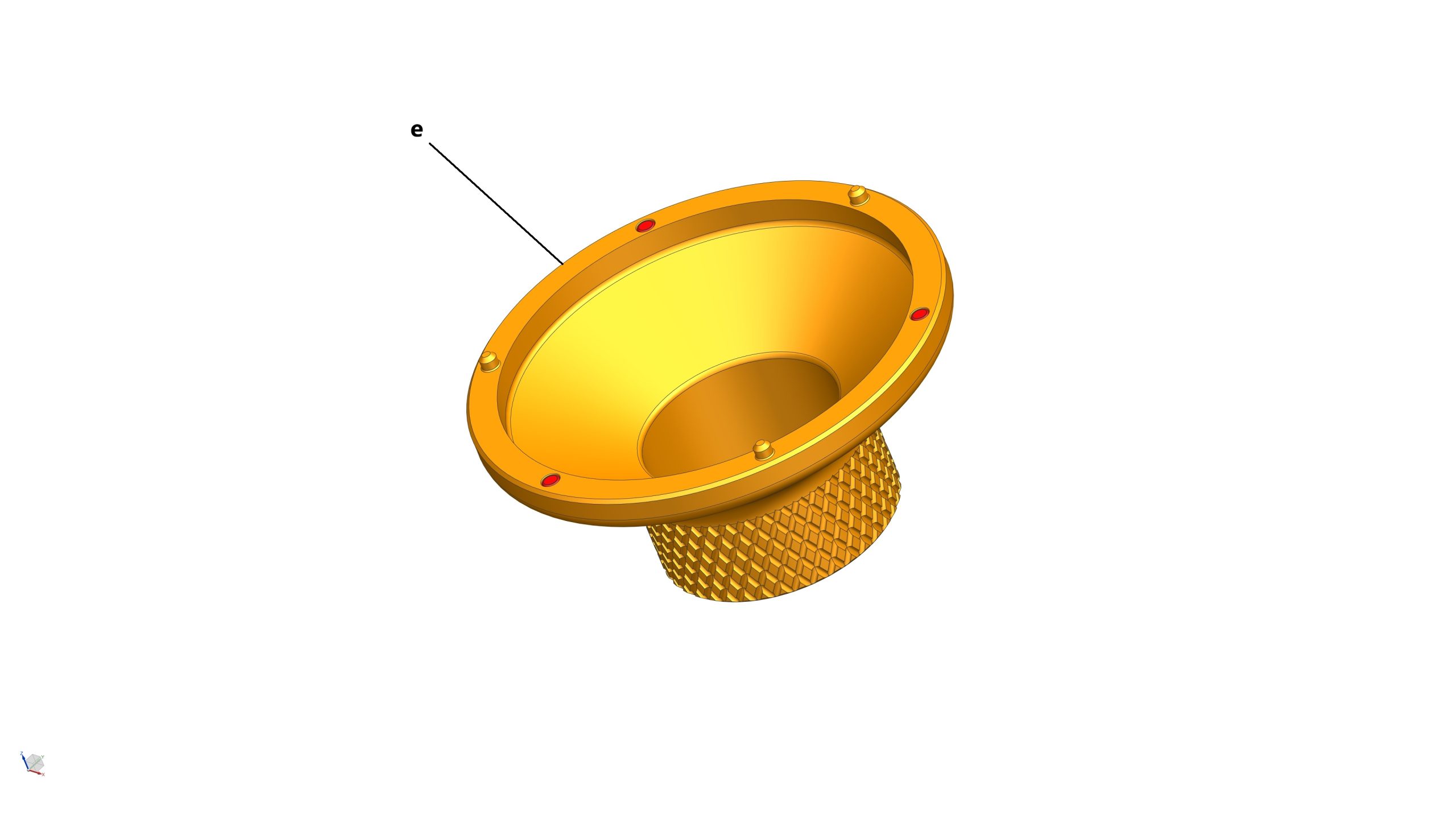
- 1x Turning Tool (e)
- 6x Magnets (5mm dia x 3mm thick) (highlighted in red)
Assembly process
- STEP 9a: Glue 3x magnets (5mm dia x 3mm thick) into their pockets at the bottom of the Threaded Ring
- STEP 9b: Install the Threaded Ring to the Inner Ring by turning it from the bottom of the Inner Ring
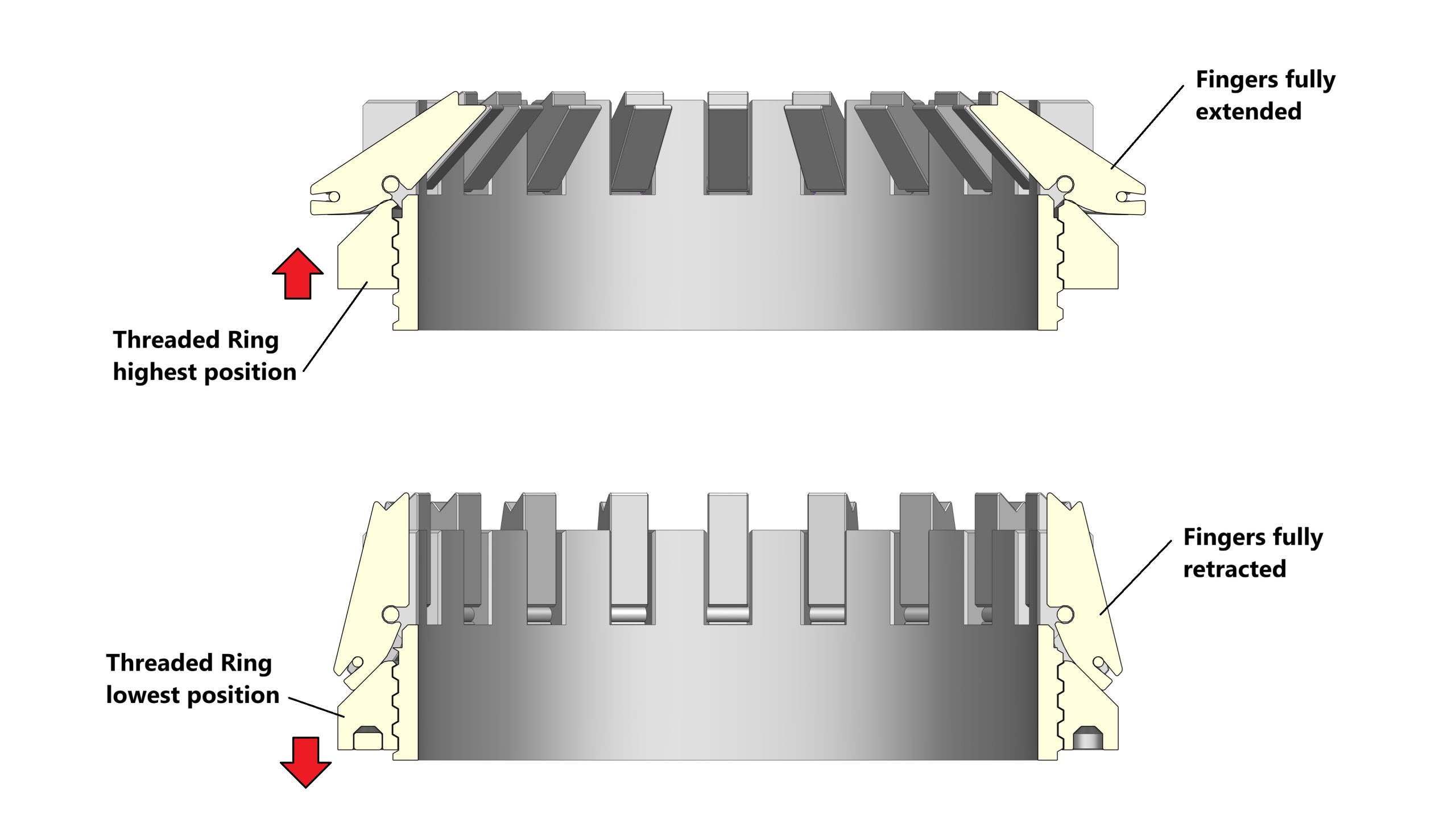
- STEP 9c: Install all 20x Fingers to the Inner Ring
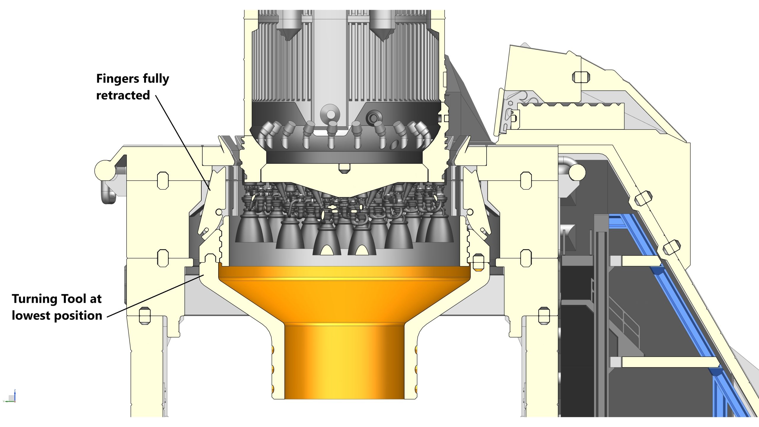
- STEP 9d: Stretch an elastic band (use more than one if needed) and insert it into the cut-out slot at the bottom of each Finger. As the rubber band is being stretched, its tension keeps all 20x Fingers in contact with the Threaded Ring at all times.
Note: At this STEP, you can test if the Fingers are working as intended by turning the Threaded Ring, as it travels from the lowest to highest position, the Fingers should move from their fully retracted to fully extended positions, and vice versa.
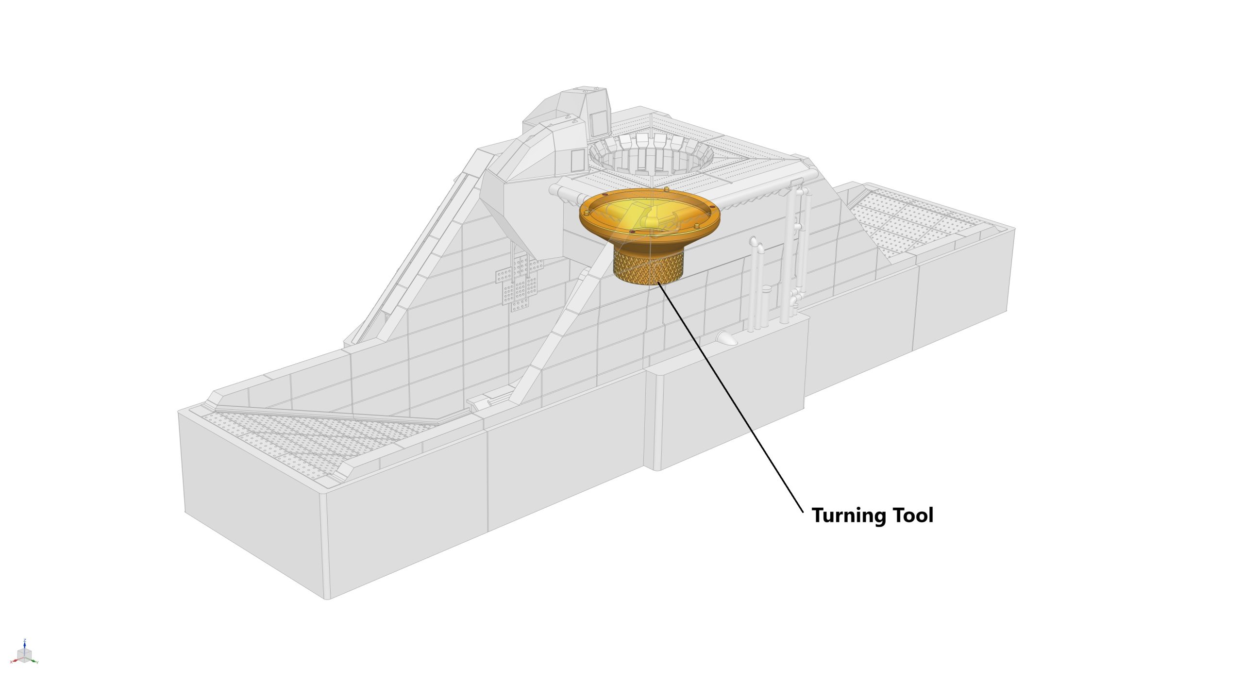
- STEP 9e: Glue 3x magnets (5mm dia x 3mm thick) into their pockets at the top of the Turning Tool. This Tool will be used to activate the Fingers once the Clamping System is installed into the Top Deck at later stage.
- STEP 9f: Test the Turning Tool by using it to turn the Threaded Ring with one hand, whilst holding the Inner Ring stationary with the other hand.
STEP 10: Assemble the Top Deck
Parts required (refer to the photos below)
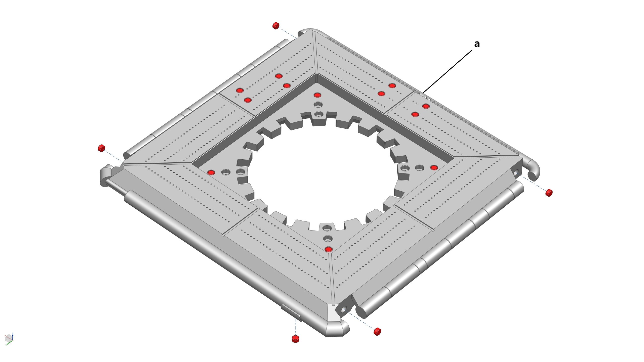
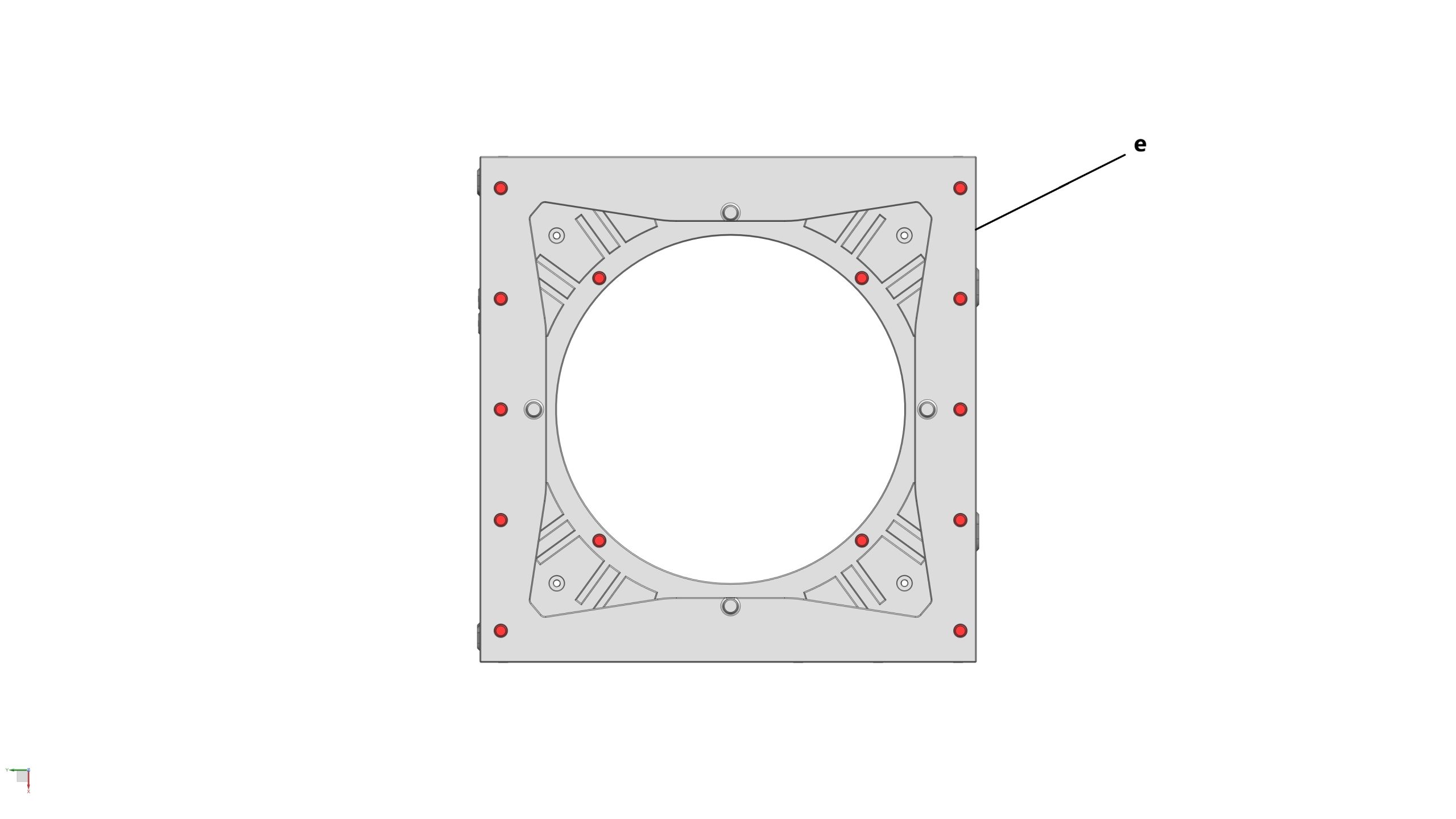
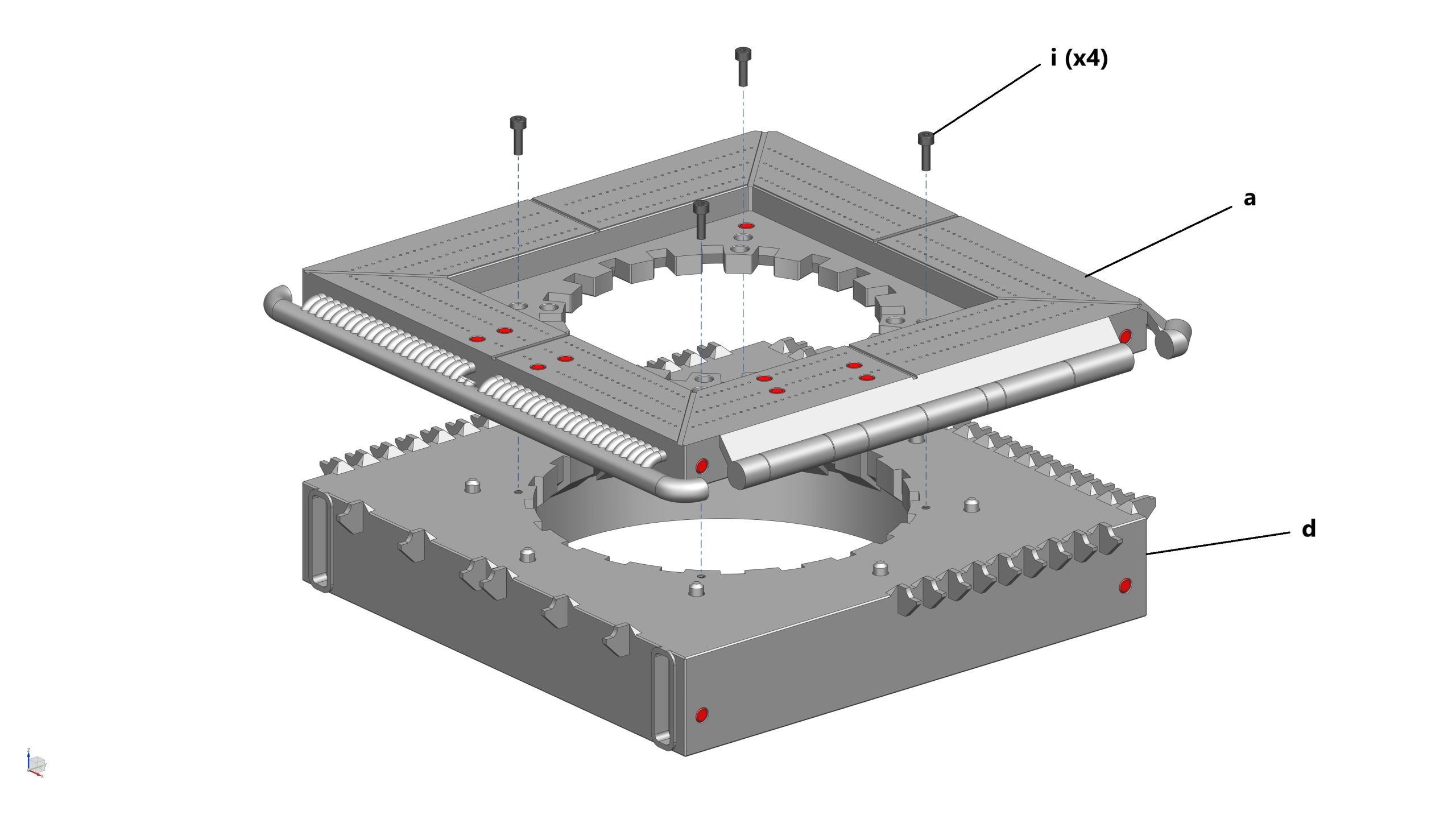
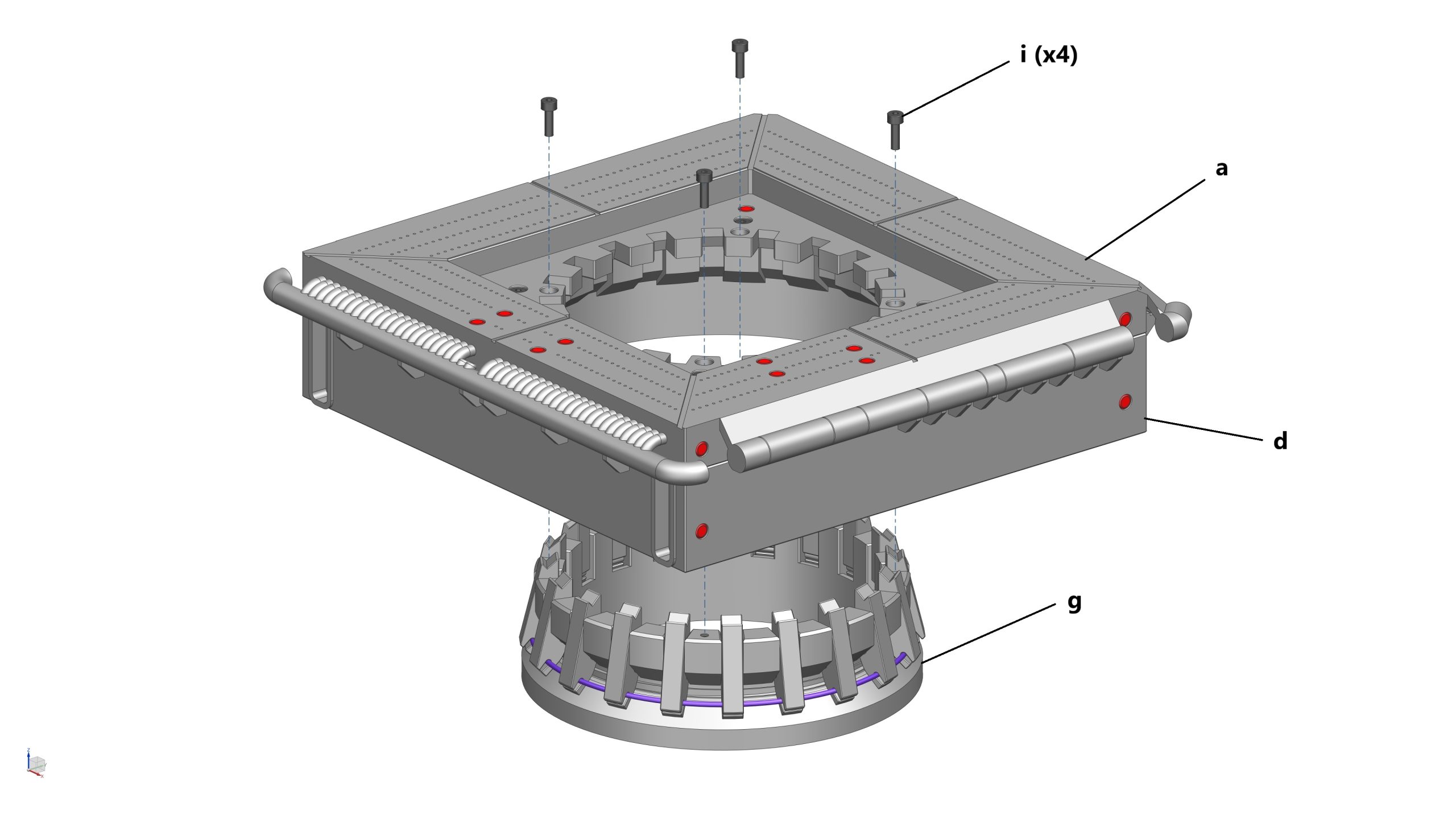
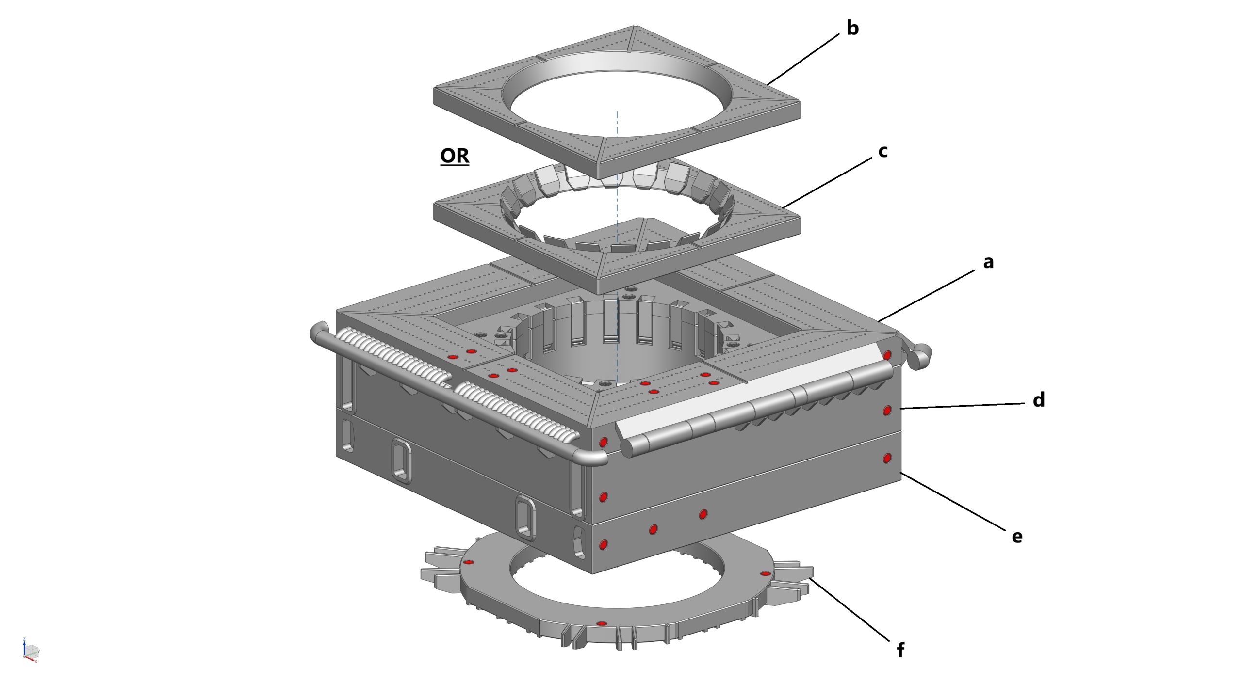
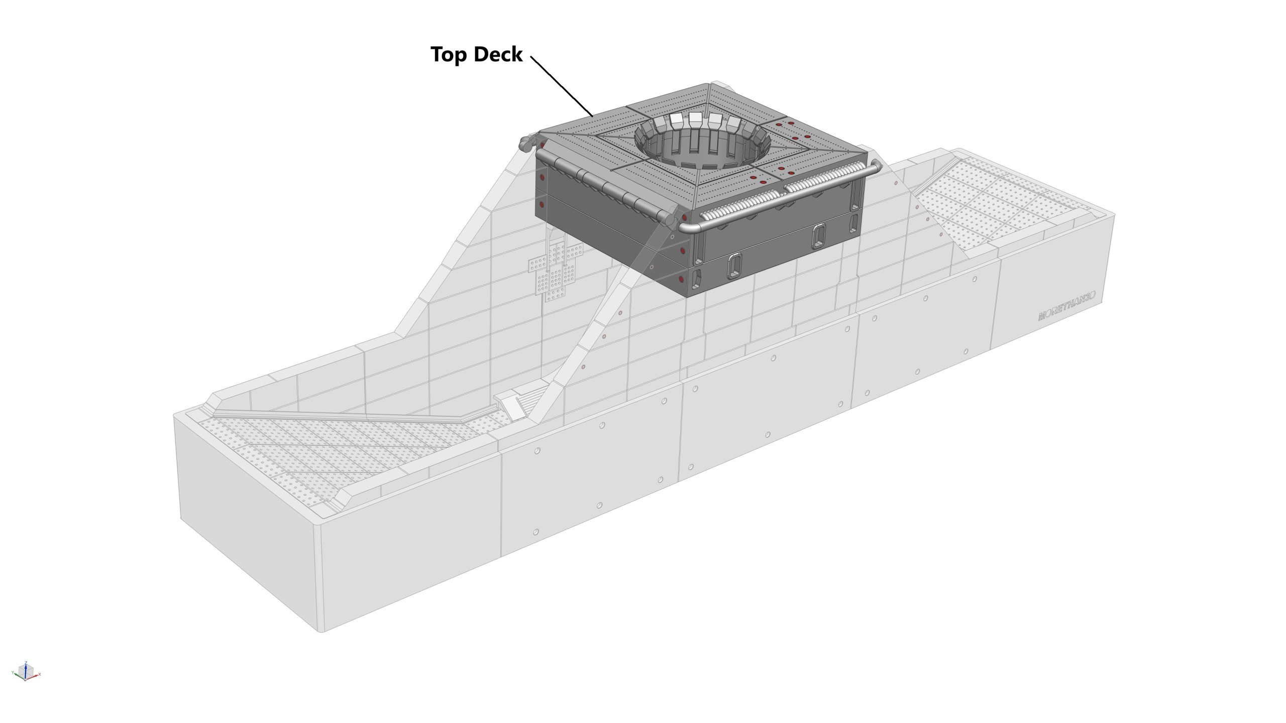
- 1x Top Deck (Upper) (a)
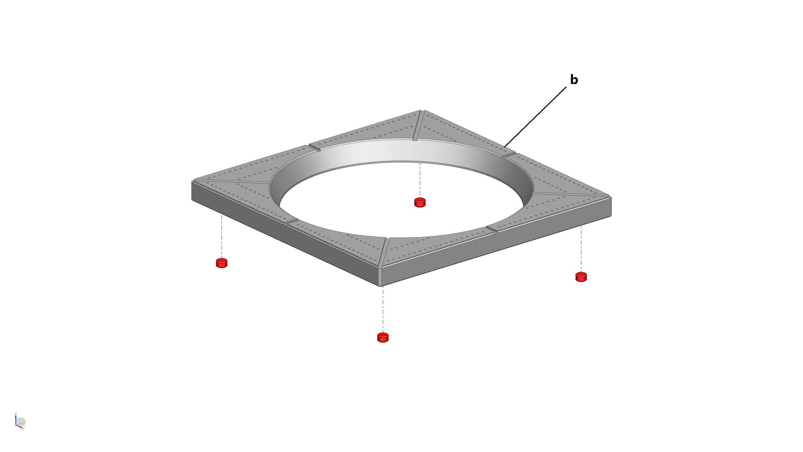
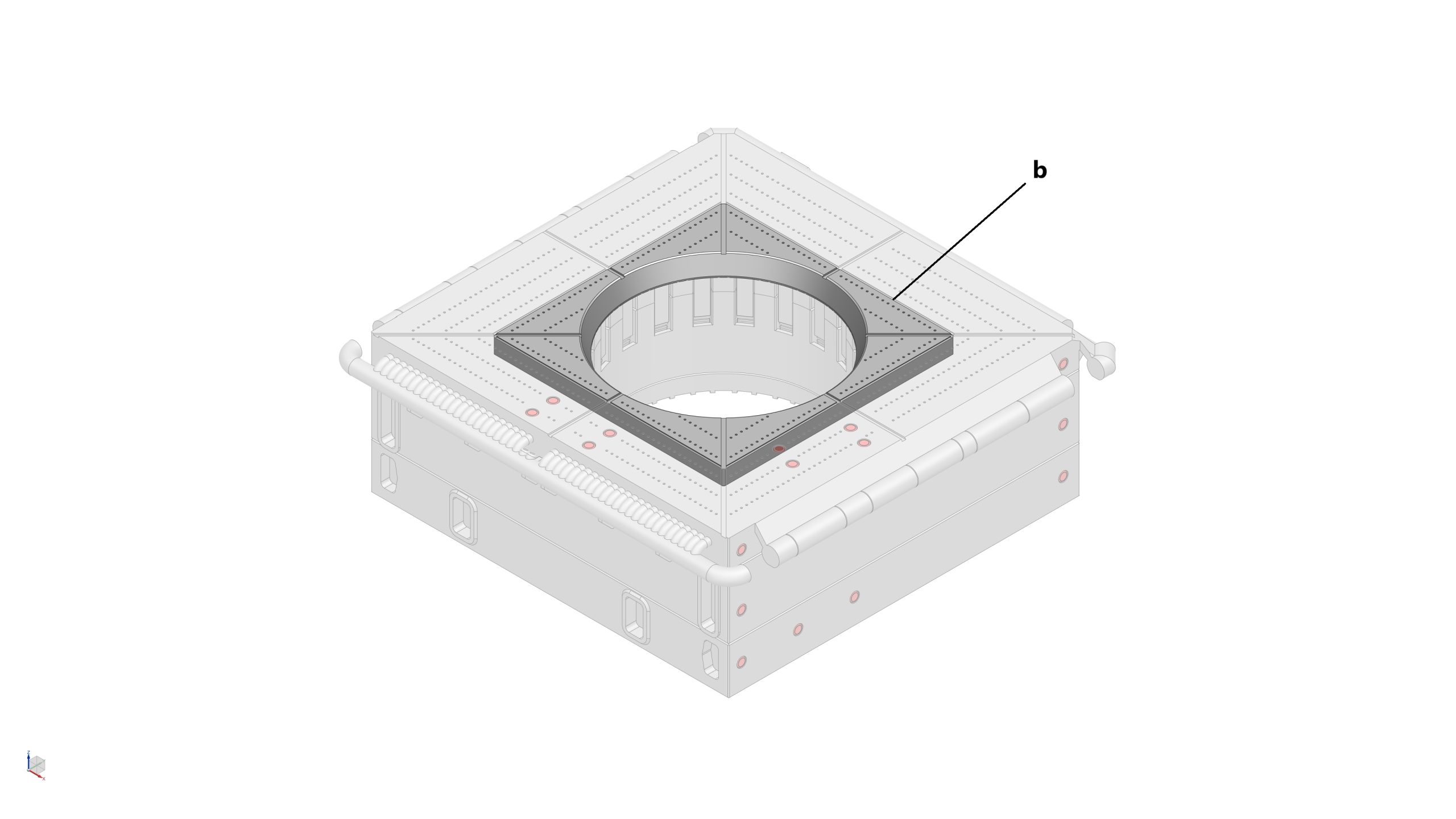
- 1x Top Deck (Upper) Center Piece_1 (b)
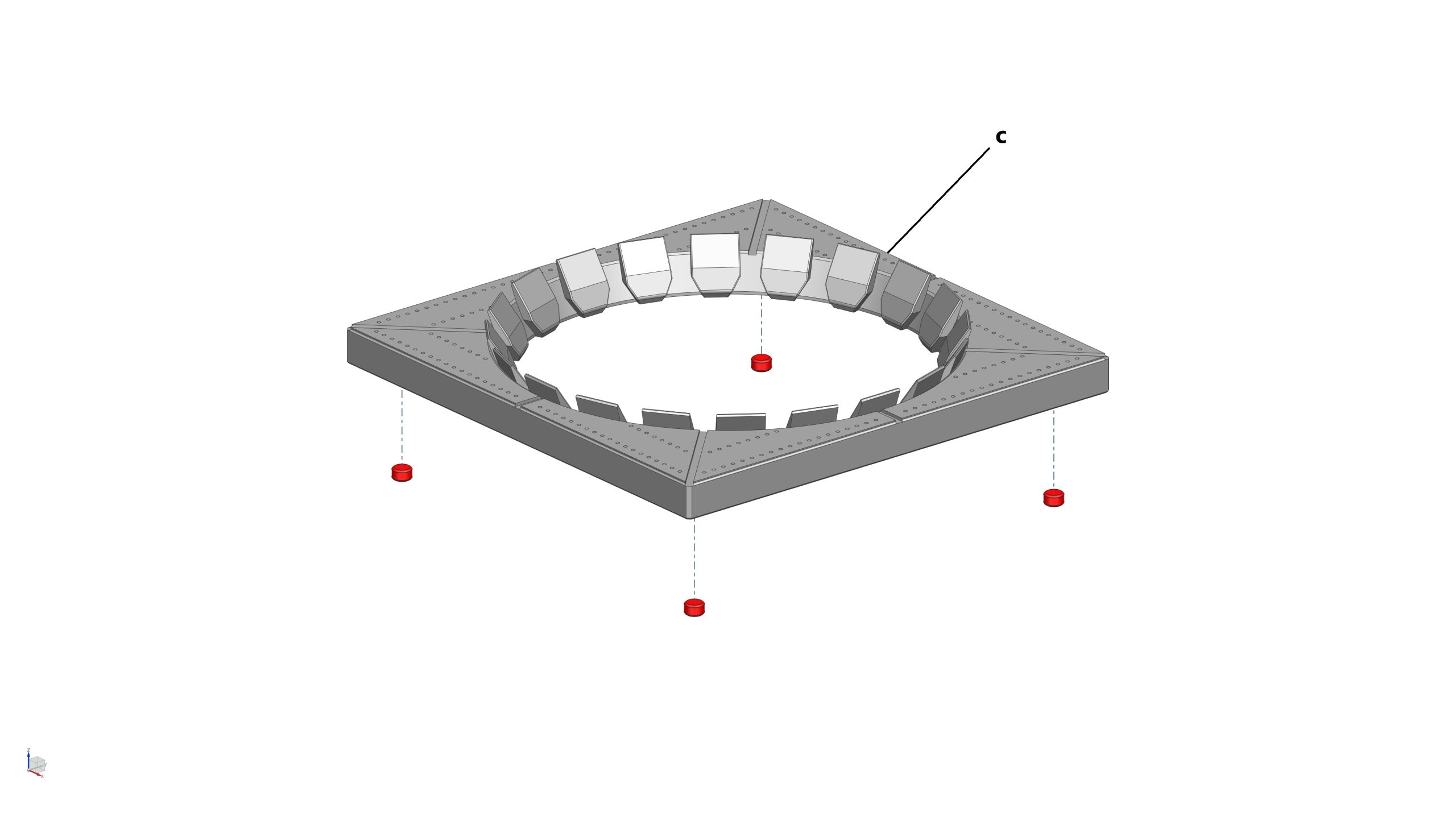
- 1x Top Deck (Upper) Center Piece_2 (c)
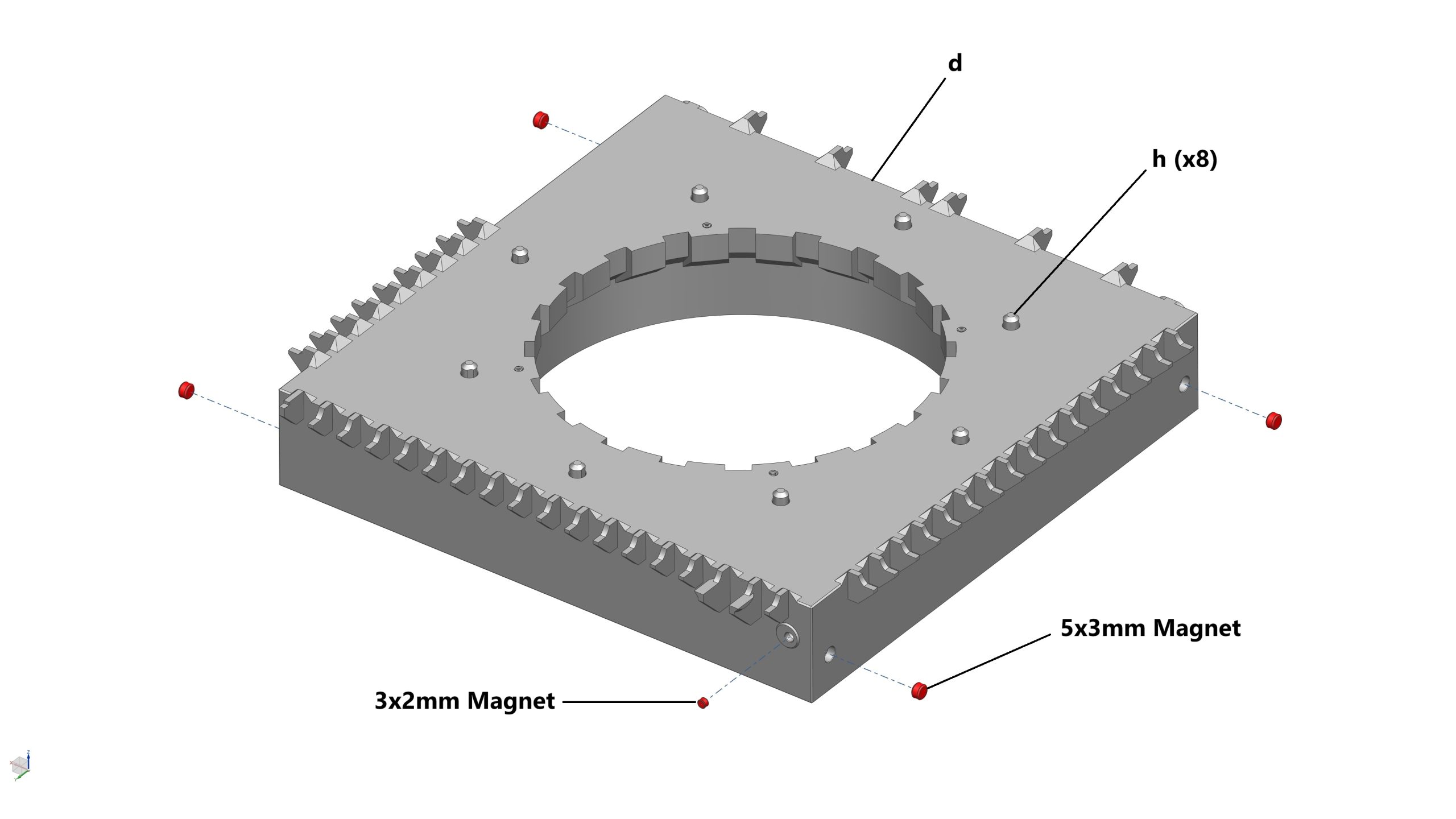
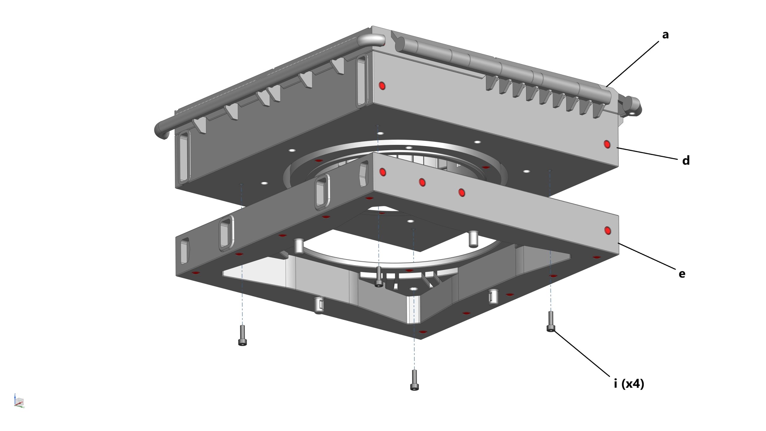
- 1x Top Deck (Middle) (d)
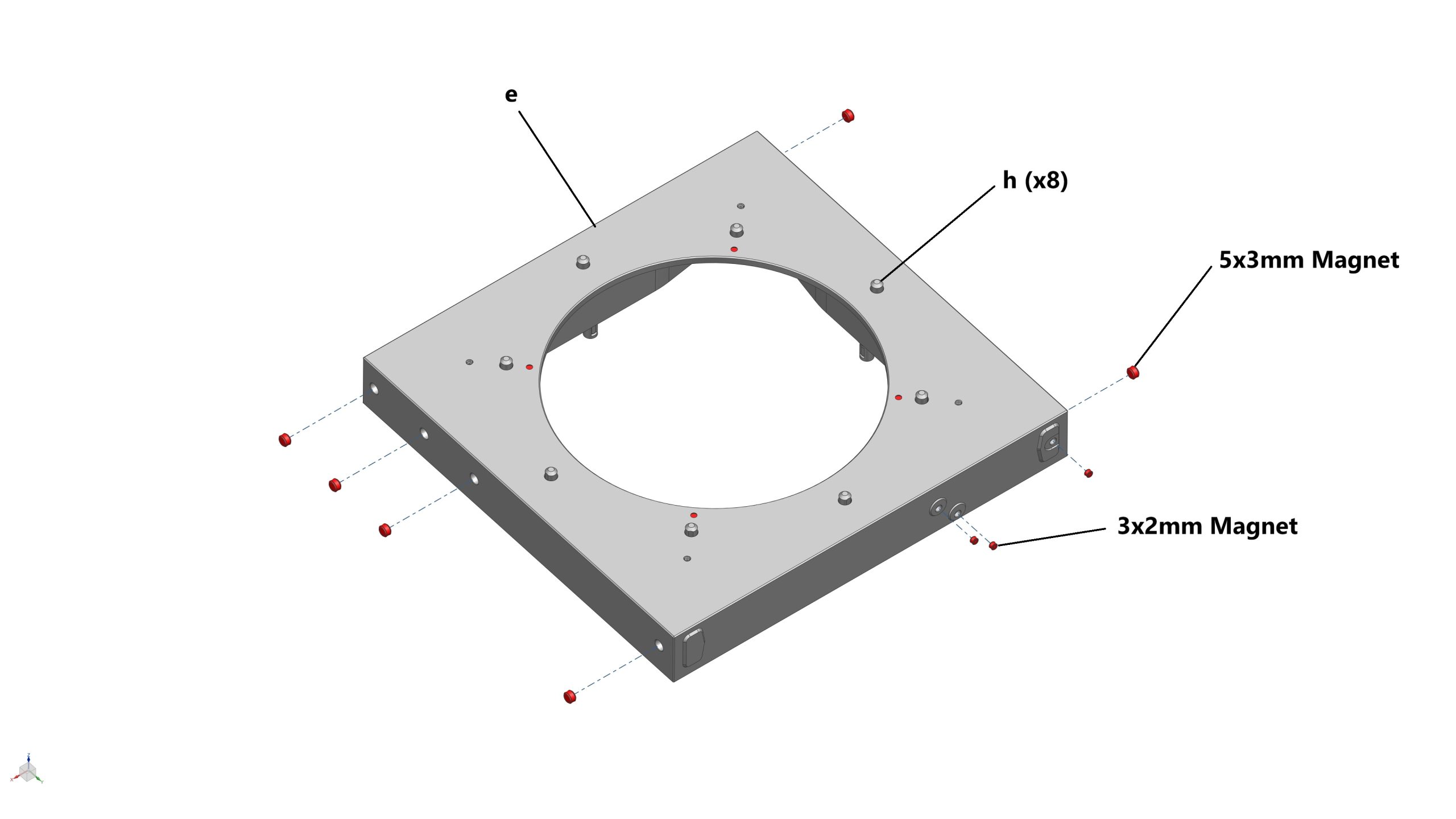
- 1x Top Deck (Lower) (e)
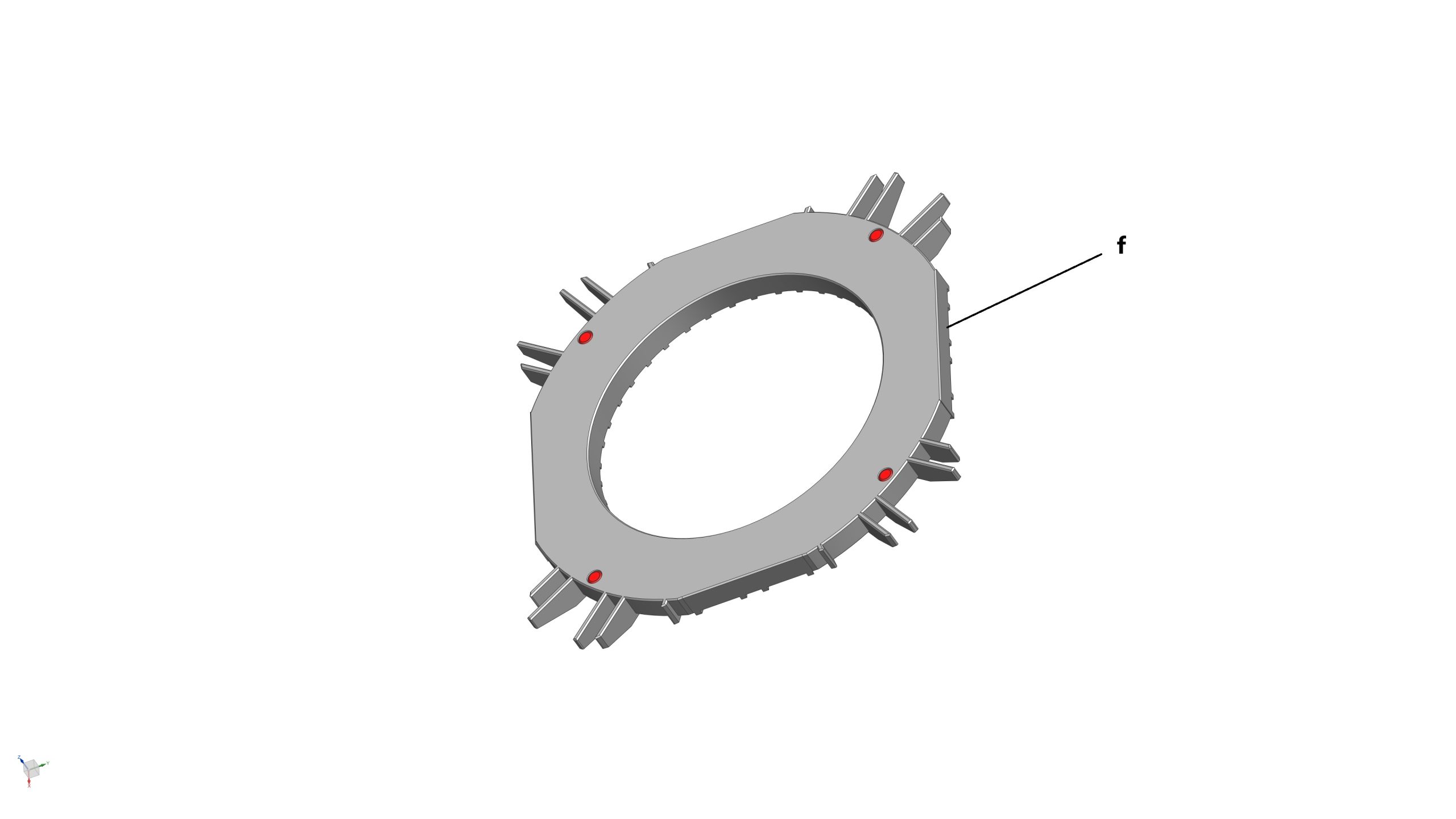
- 1x Top Deck (Lower) Centre Piece (f)
- 1x Clamping System from STEP 9 (g)
- 16x Location Pin (h)
- 12x M3 x 10mm Hex Socket Cap Screw (i)
- 4x Magnet (3mm dia x 2mm thick) (highlighted in red)
- 53x Magnet (5mm dia x 3mm thick) (highlighted in red)
Assembly process
- STEP 10a: Glue 17x magnets (5mm dia x 3mm thick) into their pockets at the top (x12), side (x4), and bottom (x1) faces of the Top Deck (Upper)
- STEP 10b: Glue 4x magnets (5mm dia x 3mm thick) into their pockets at the bottom face of the Top Deck (Upper) Center Piece_1
- STEP 10c: Glue 4x magnets (5mm dia x 3mm thick) into their pockets at the bottom face of the Top Deck (Upper) Center Piece_2
- STEP 10d: Glue 4x magnets (5mm dia x 3mm thick) and 1x magnet (3mm dia x 2mm thick) into their pockets at the sides of the Top Deck (Middle). Insert 8x Locating Pins to the top face of the Top Deck (Middle)
- STEP 10e: Glue 14x magnets (5mm dia x 3mm thick) into their pockets at the bottom face of the Top Deck (Lower)
- STEP 10f: Glue 6x magnets (5mm dia x 3mm thick) and 3x magnets (3mm dia x 2mm thick) into their pockets at the sides of the Top Deck (Lower). Insert 8x Locating Pins to the top face of the Top Deck (Lower)
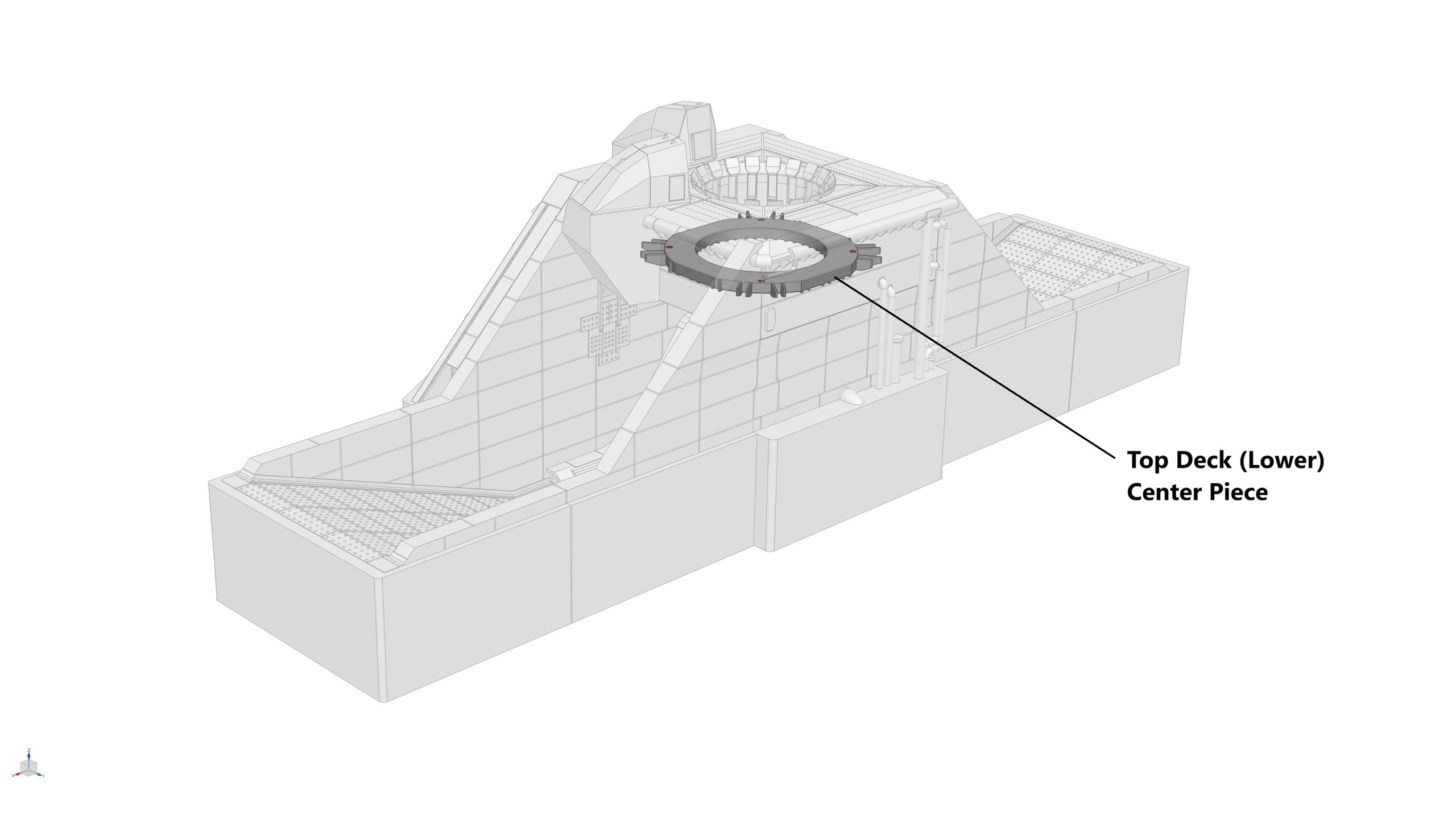
- STEP 10g: Glue 4x magnets (5mm dia x 3mm thick) into their pockets at the top face of the Top Deck (Lower) Center Piece
IMPORTANT: DO NOT glue the Top Deck (Lower) and Top Deck (Lower) Center Piece together. The Top Deck (Lower) Center Piece must be keep detachable from the Top Deck (Lower) to gain access to the Clamping System – which is crucial to activate the Fingers (a.k.a. Booster hold down clamps)
- STEP 10h: Assemble the Top Deck (Upper) to the Top Deck (Middle) together using four M3 x 10mm Hex Socket Cap Screws
- STEP 10i: Assemble the Clamping System from STEP 9 to the Top Deck (Upper) using four M3 x 10mm Hex Socket Cap Screws
- STEP 10j: Assemble the Top Deck (Lower) to the Top Deck (Middle) together using four M3 x 10mm Hex Socket Cap Screws
- STEP 10k: Install either the Top Deck (Upper) Center Piece_1 or 2 to the Top Deck (Upper)
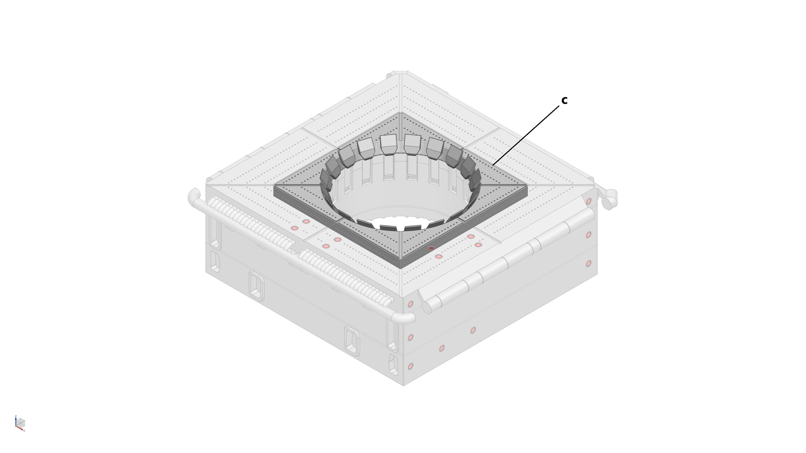
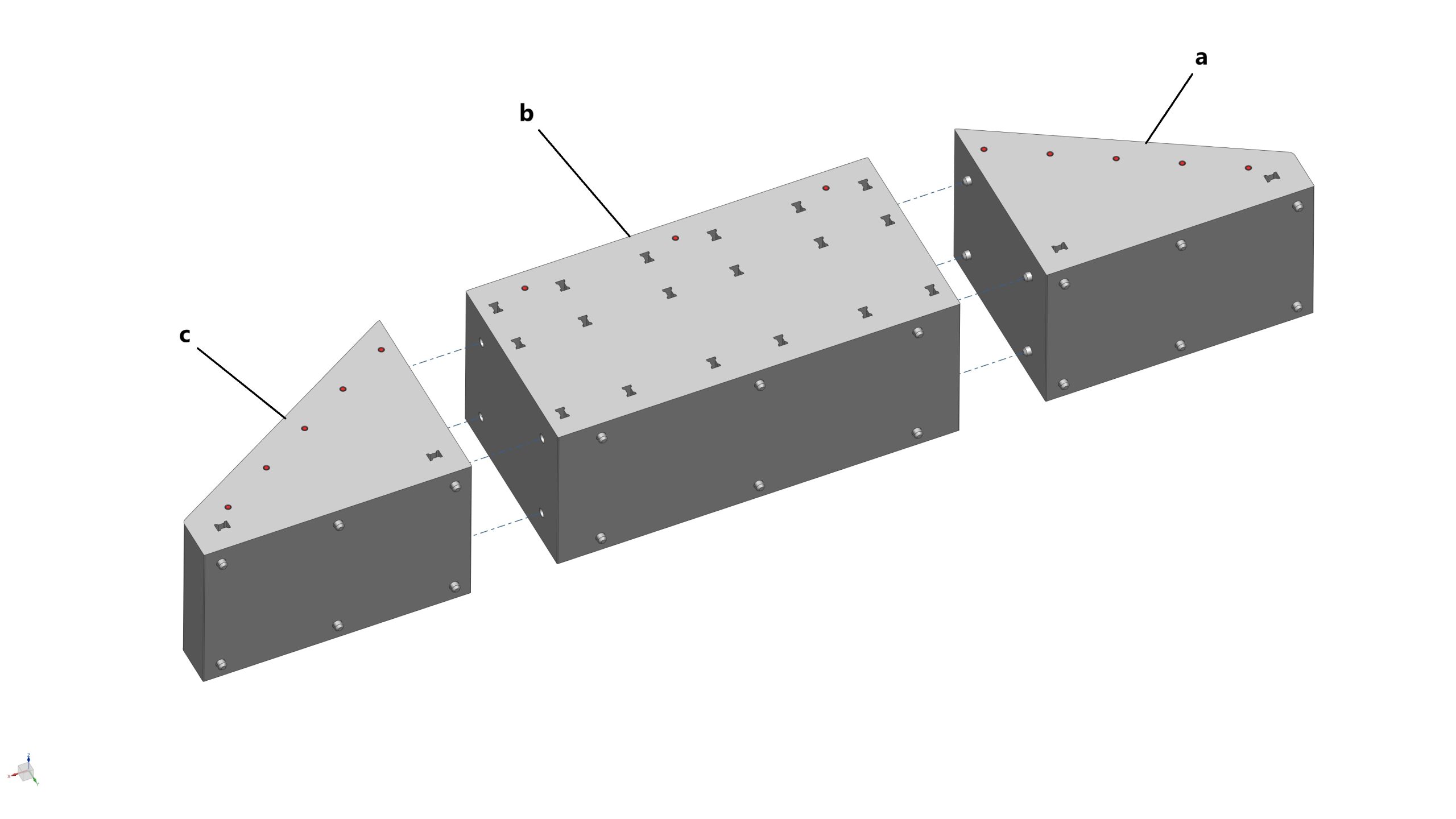
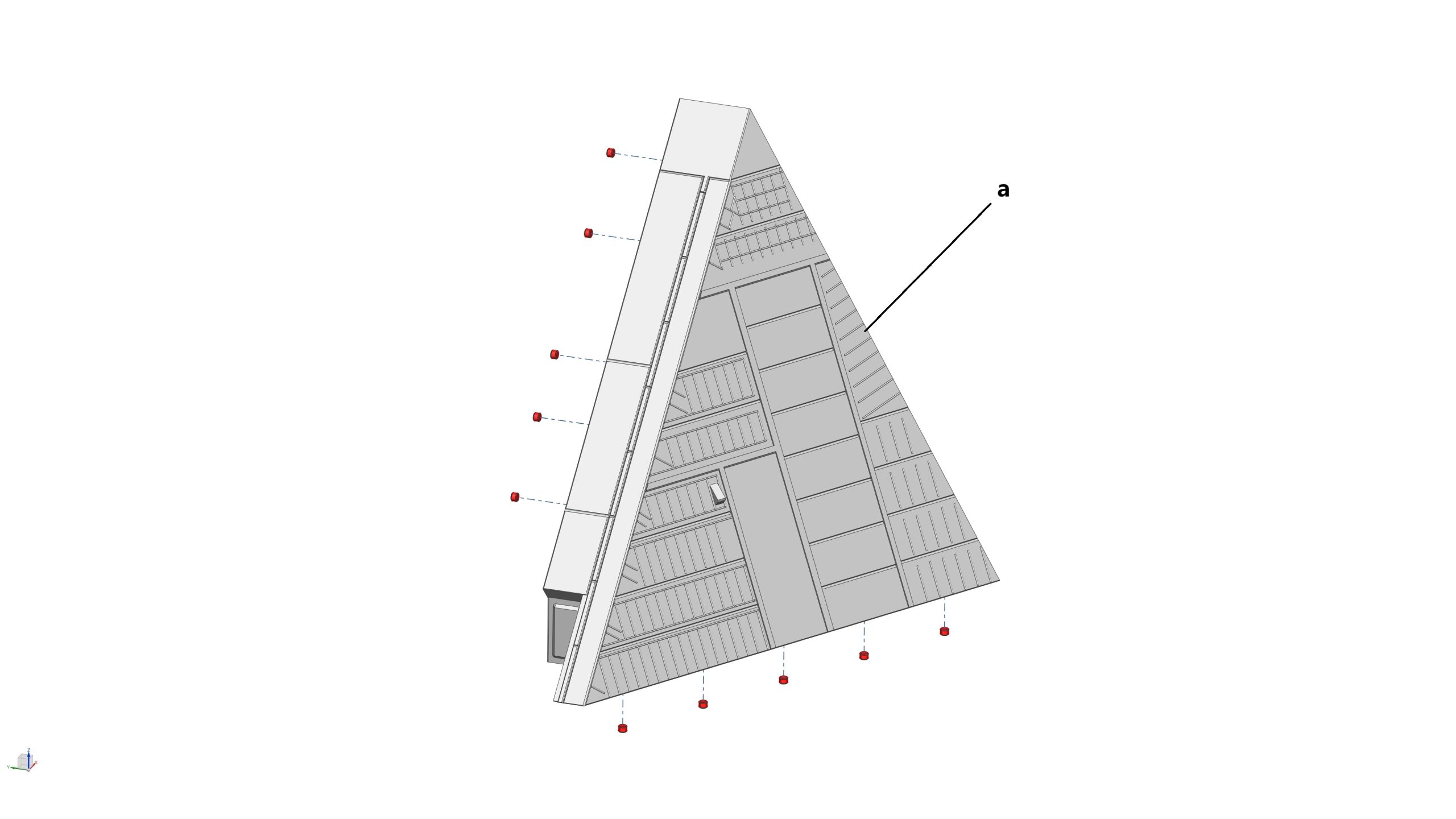
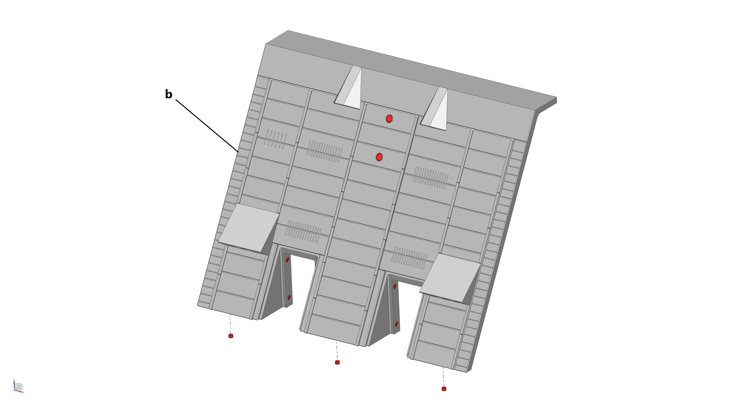
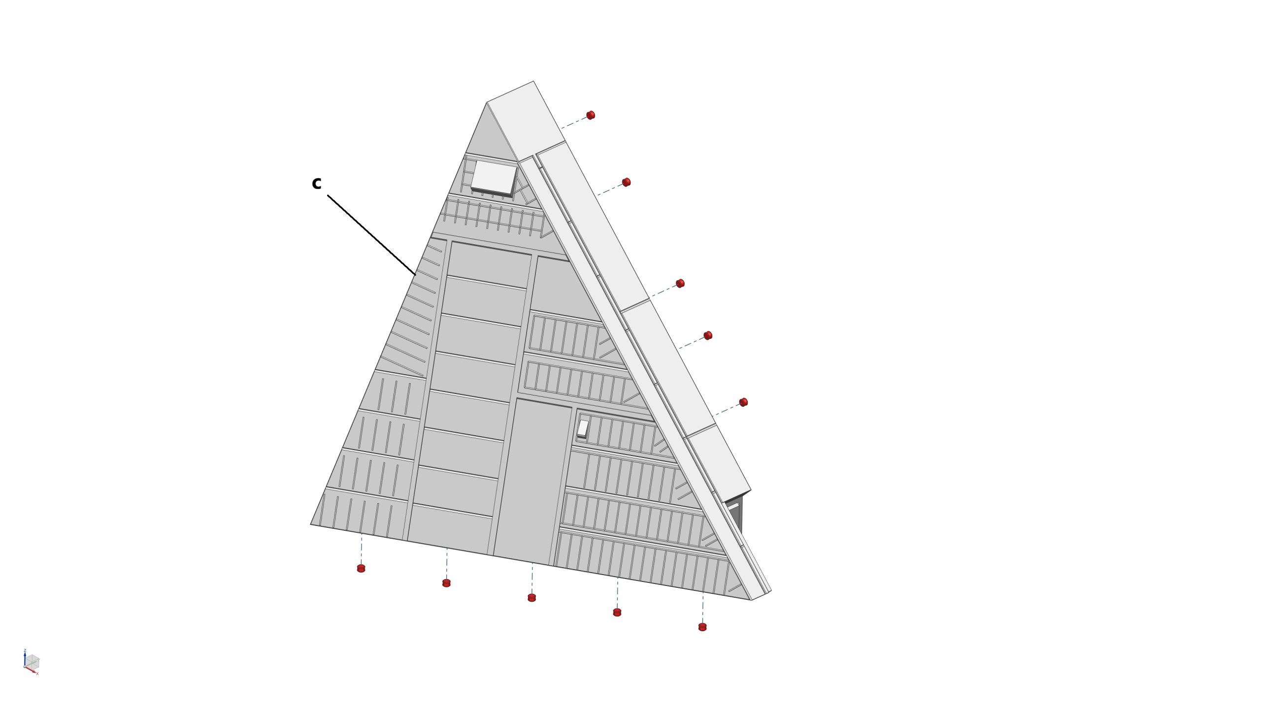
STEP 11: Assemble the GSE Bunker Foundation
Parts required (refer to the photos below)
- 1x Block 6 (a)
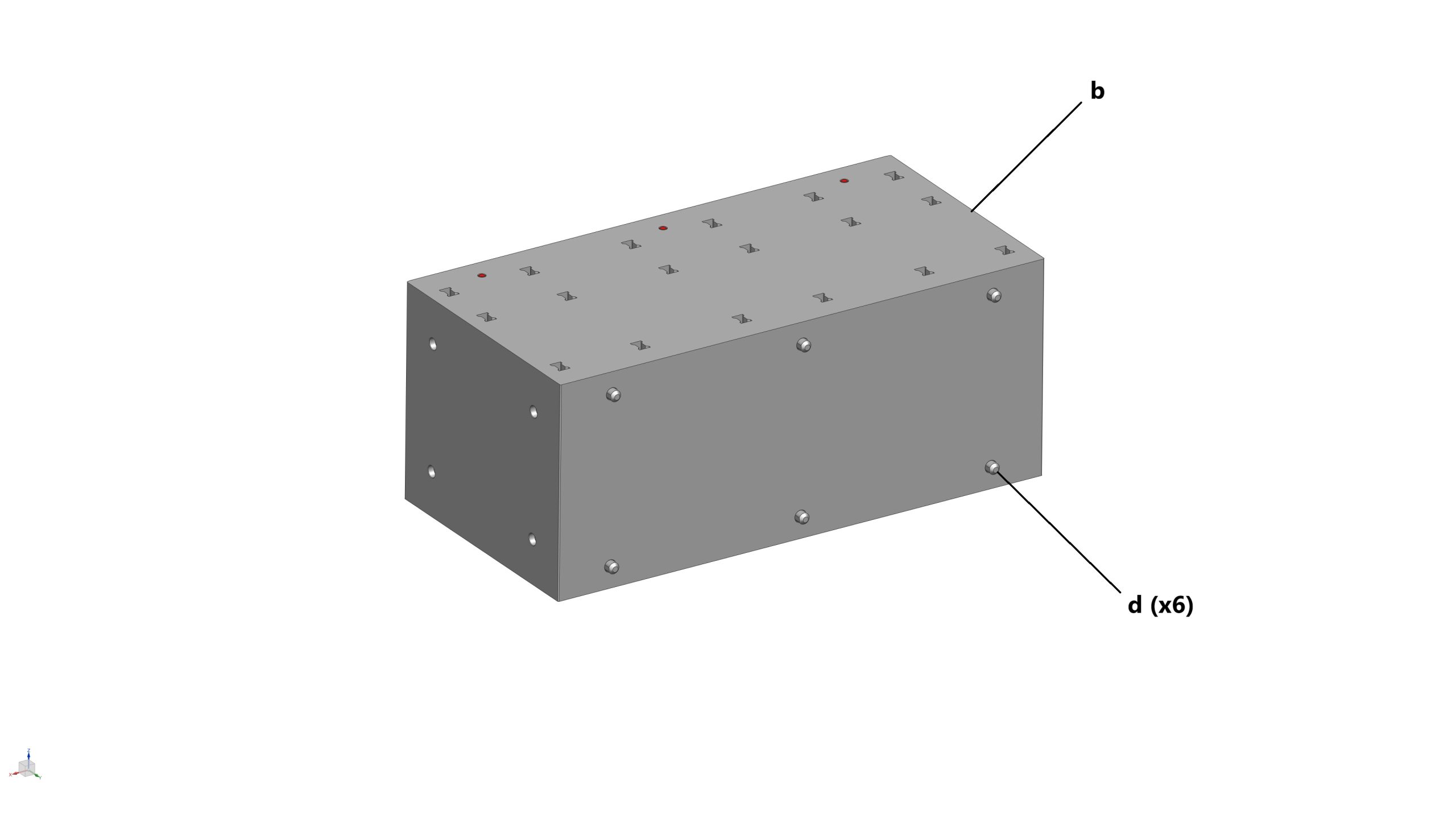
- 1x Block 7 (b)
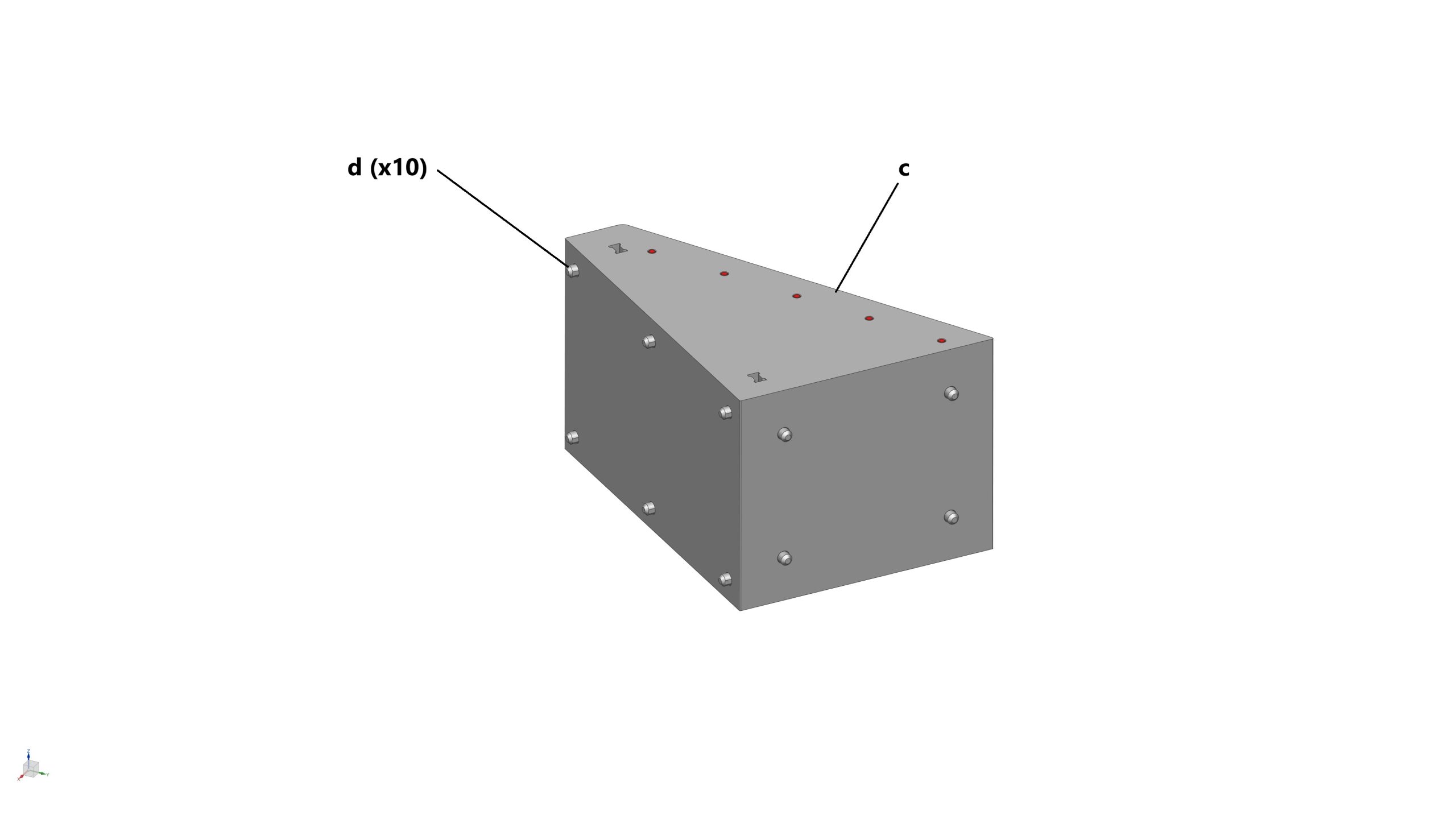
- 1x Block 8 (c)
- 26x Locating Pin (d)
- 13x Magnet (3mm dia x 2mm thick) (highlighted in red)
Assembly process
- STEP 11a: Glue 5x magnet (3mm dia x 2mm thick) into their pockets at the top of Block 6. Install 10x Locating Pins to the back (x6) and side (x4) of Block 6.
- STEP 11b: Glue 3x magnet (3mm dia x 2mm thick) into their pockets at the top of Block 7. Install 6x Locating Pins to the back Block 7.
- STEP 11c: Glue 5x magnet (3mm dia x 2mm thick) into their pockets at the top of Block 8. Install 10x Locating Pins to the back (x6) and side (x4) of Block 8.
- STEP 11d: Assemble Block 6, 7, and 8 together
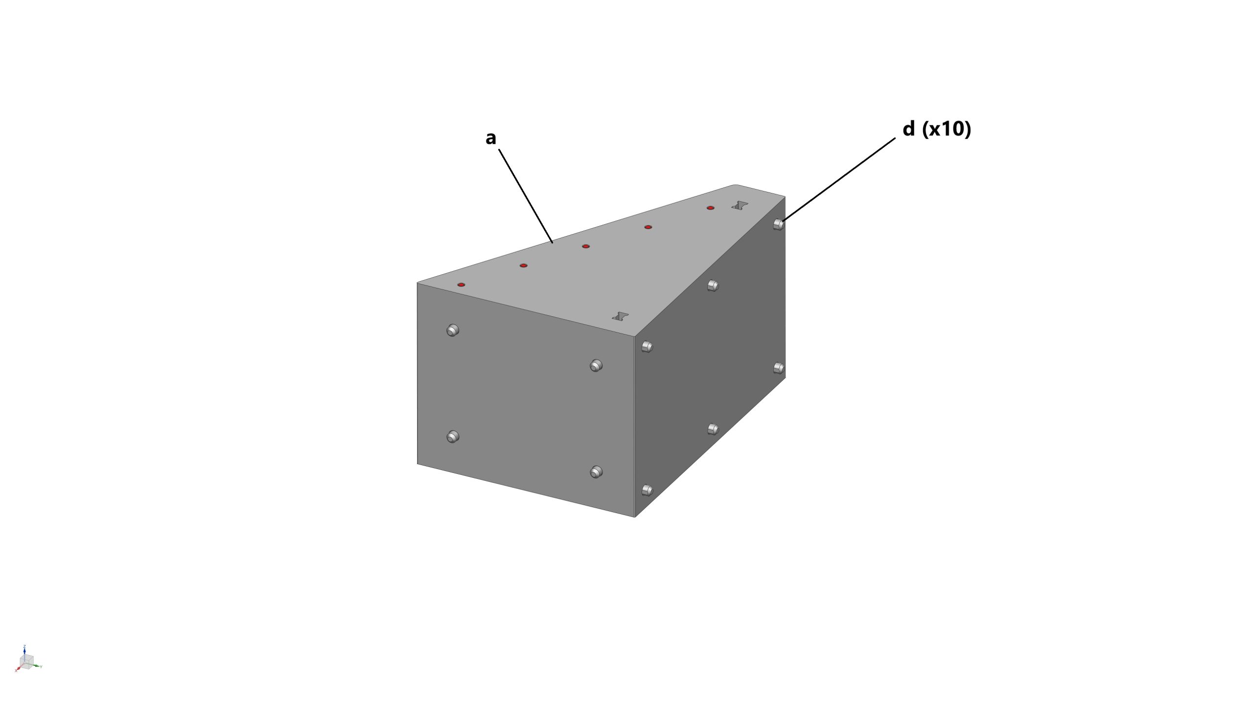
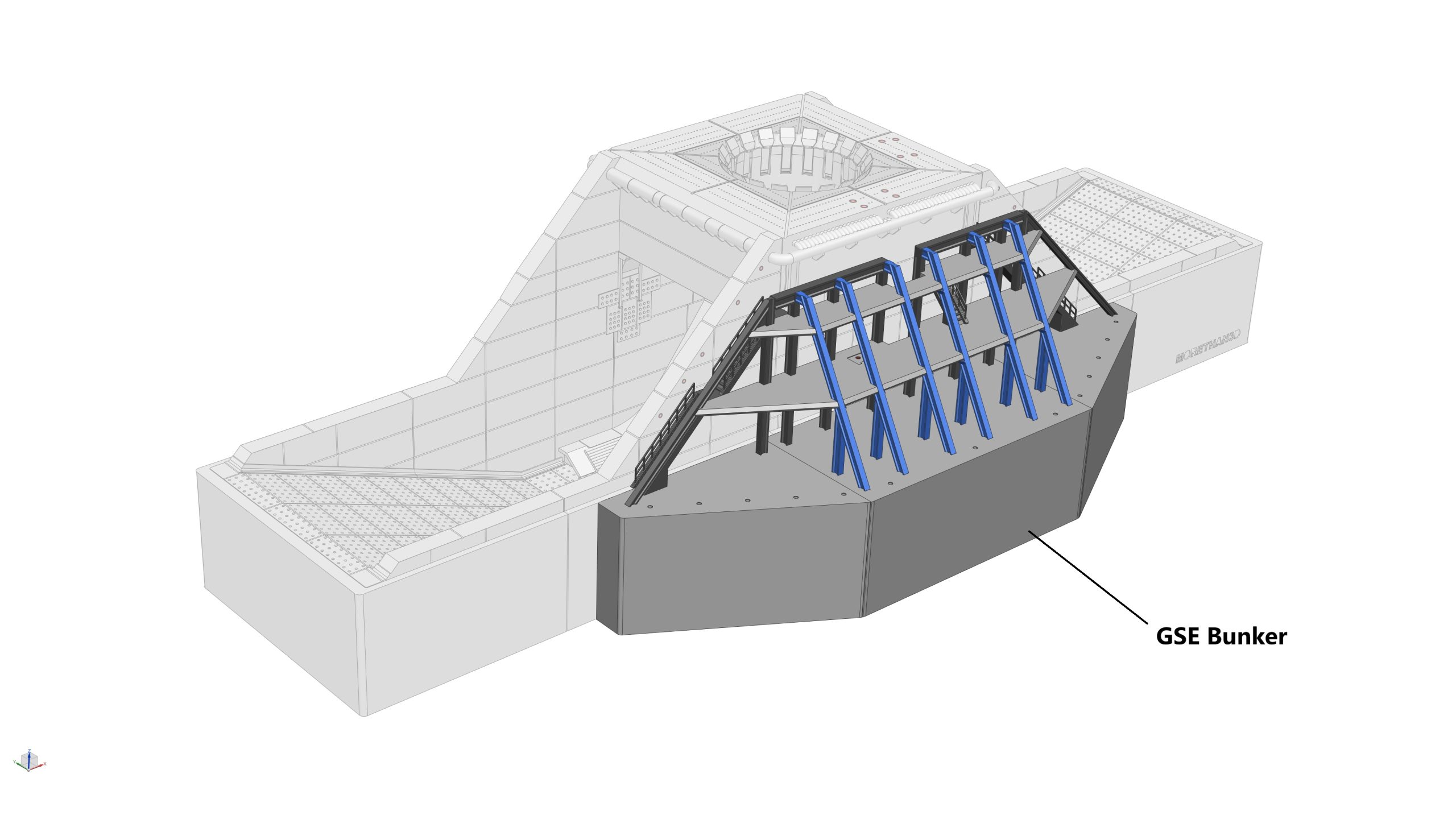
STEP 12: Assemble the GSE Bunker Gantry
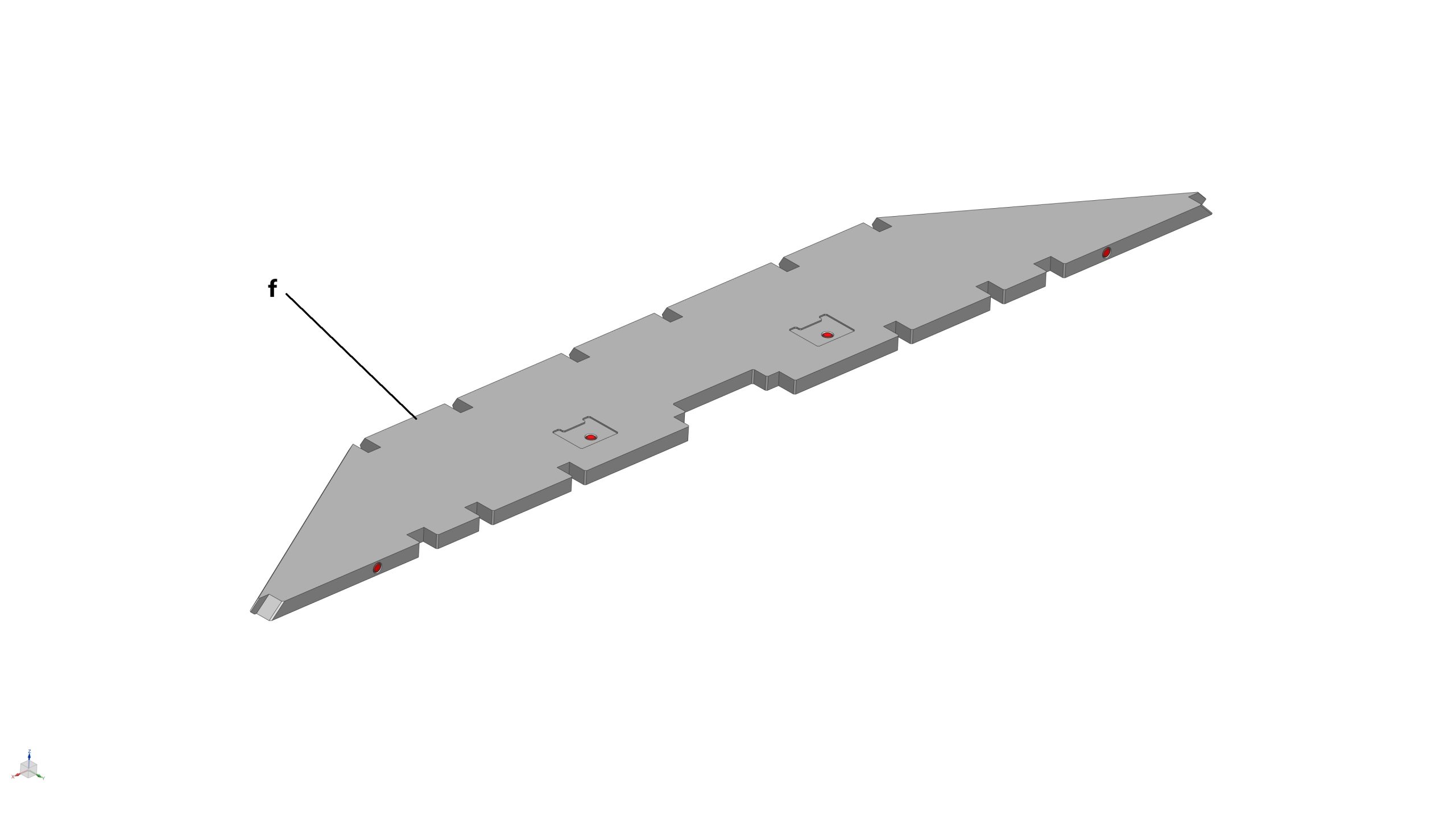
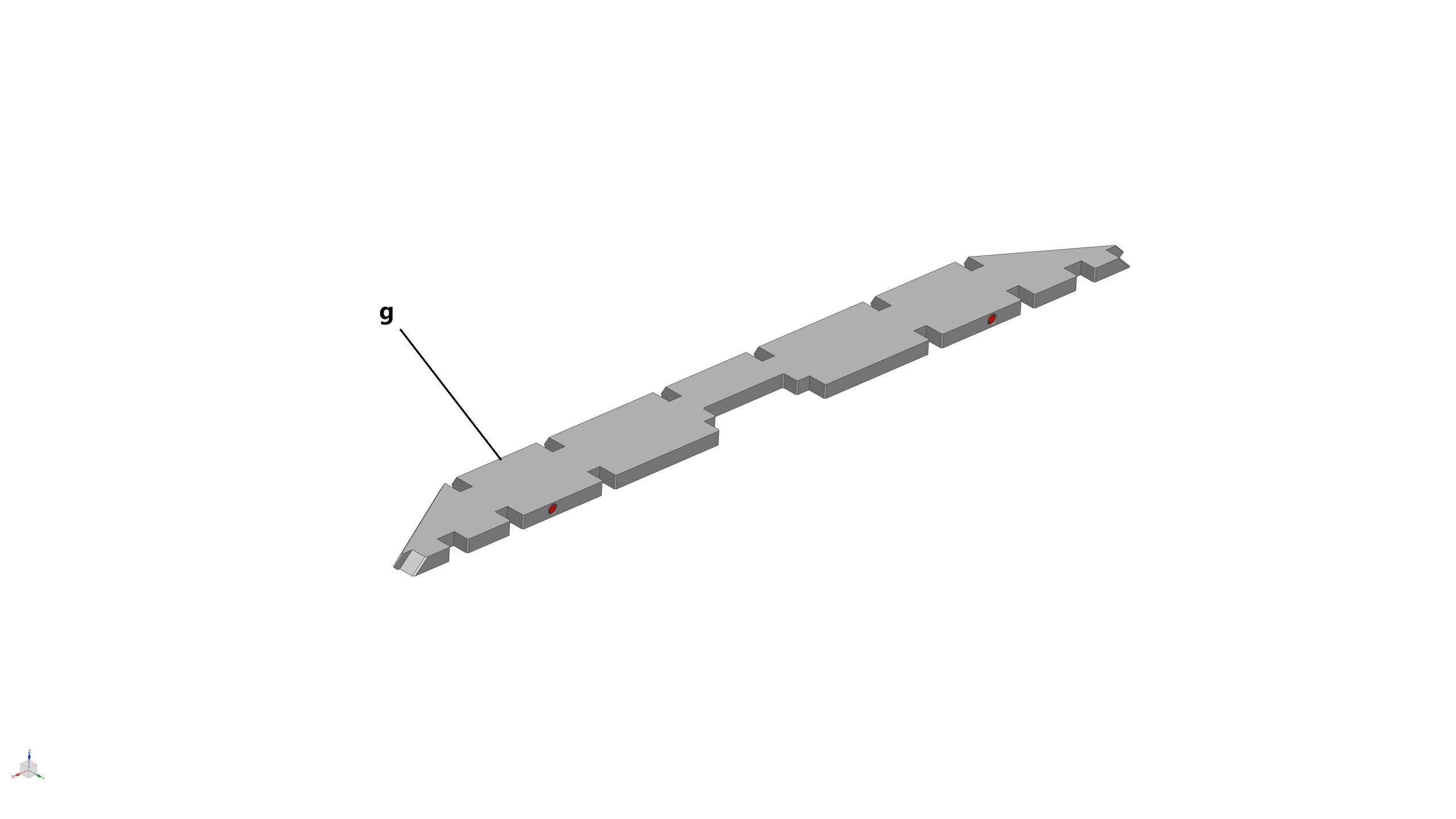
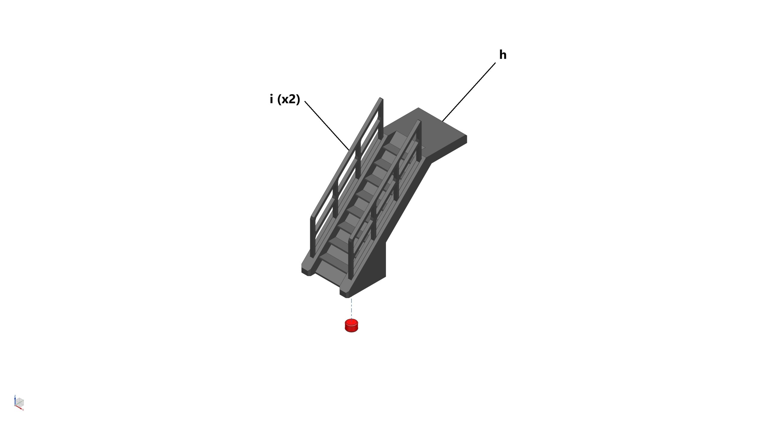
Parts required (refer to the photos below)
- 1x Beam A (LH) (a)
- 1x Beam A (RH) (b)
- 3x Beam B (LH) (c)
- 3x Beam B (RH) (d)
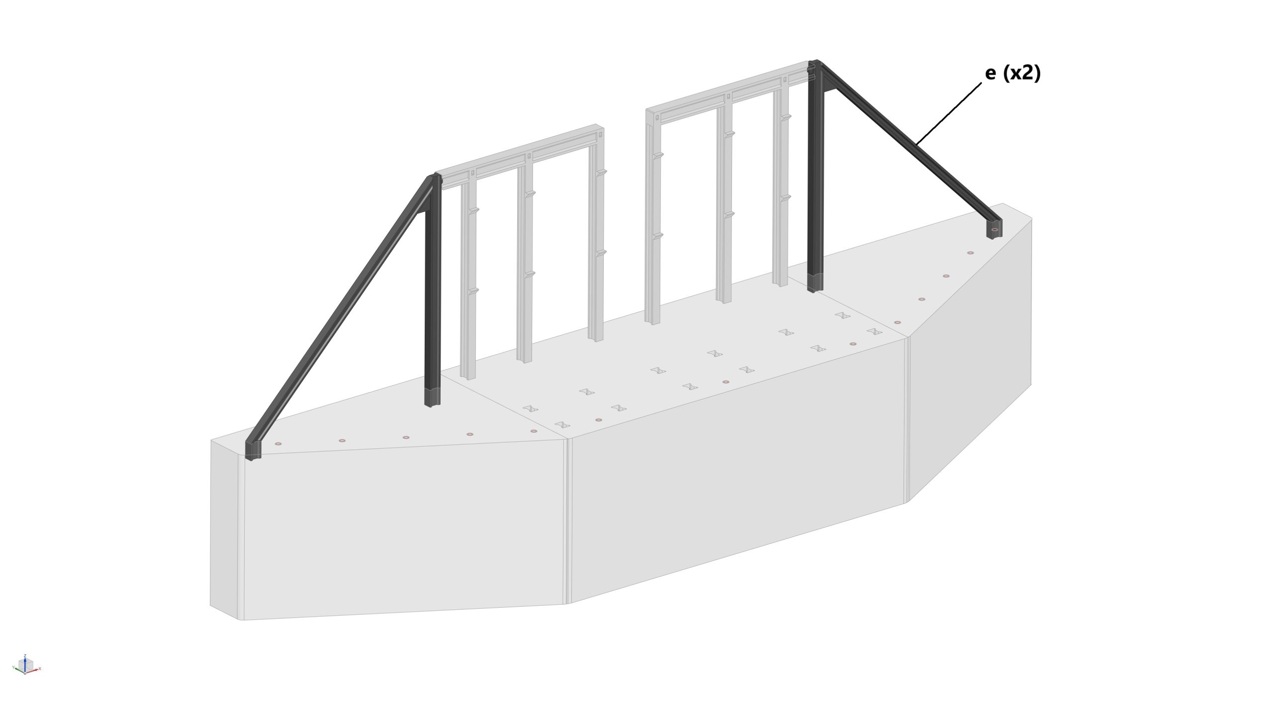
- 2x Beam C (e)
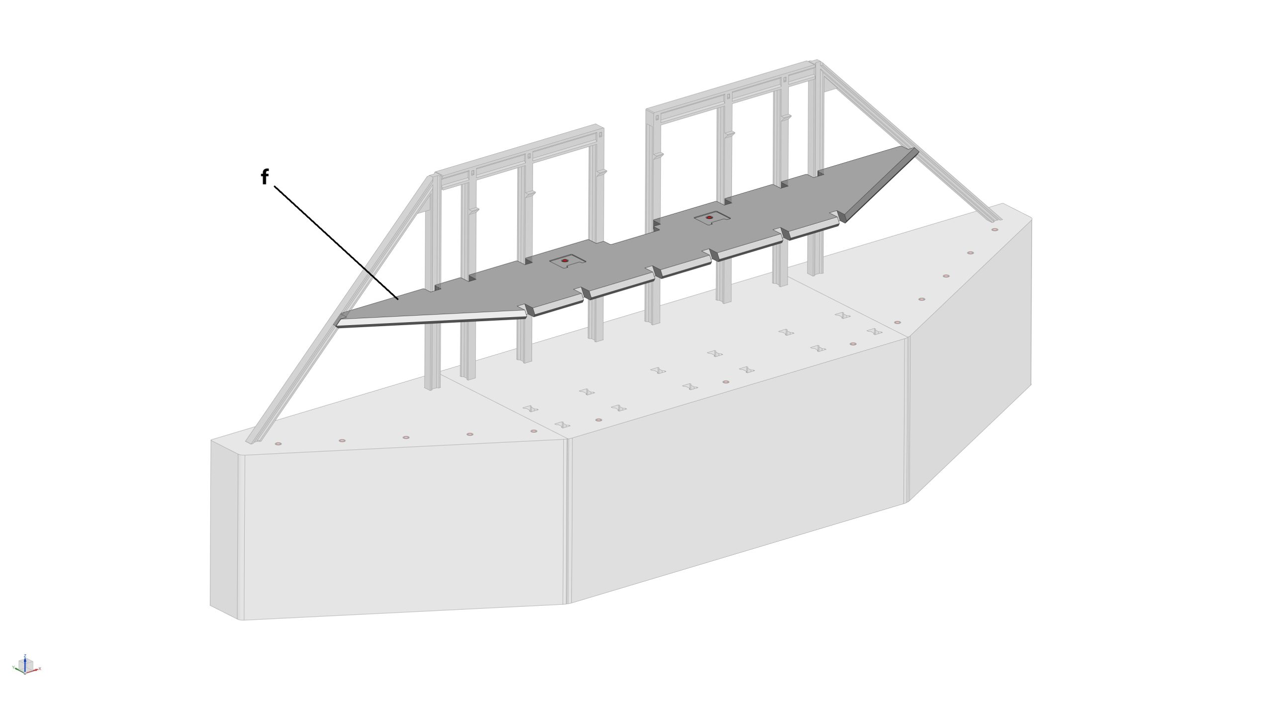
- 1x GSE Bunker 1st Floor (f)
- 1x GSE Bunker 2nd Floor (g)
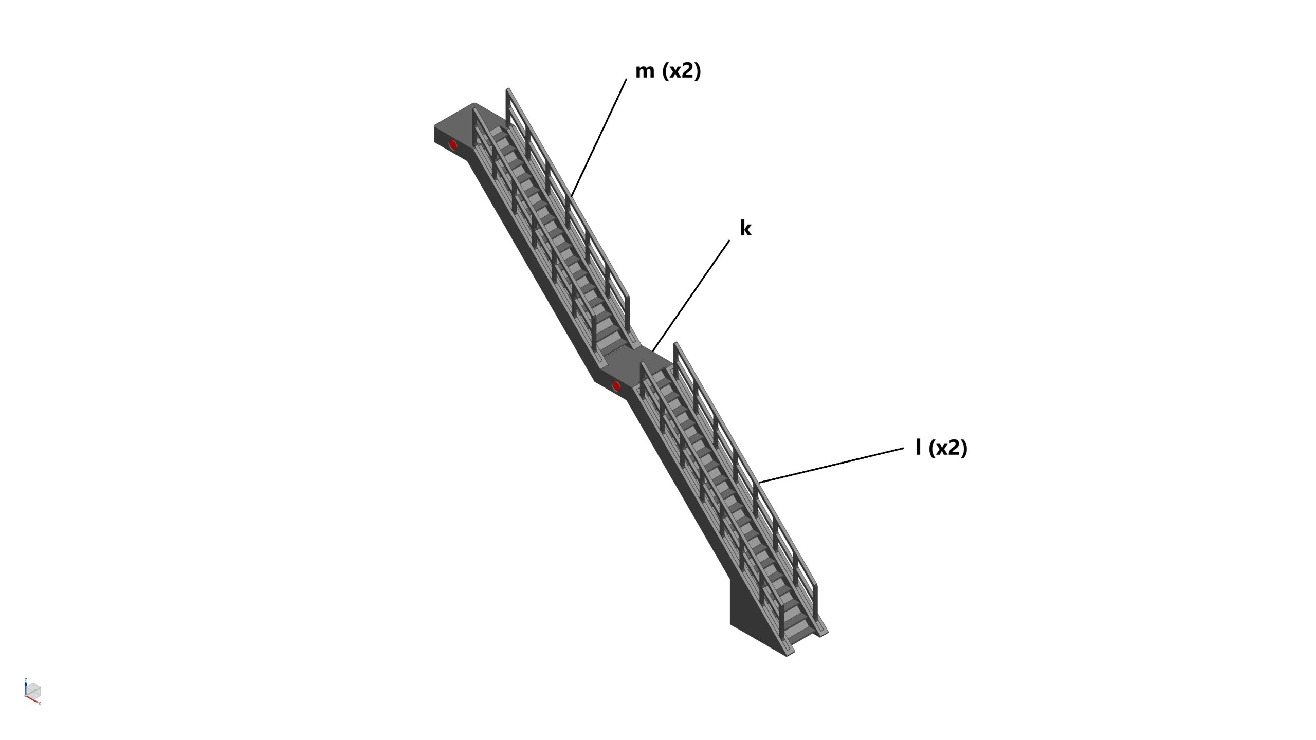
- 2x Short Stairs (h)
- 4x Short Stairs Railing (i)
- 1x Long Stairs (LH) (j)
- 1x Long Stairs (RH) (k)
- 4x Long Stairs Railing 1 (l)
- 4x Long Stairs Railing 2 (m)
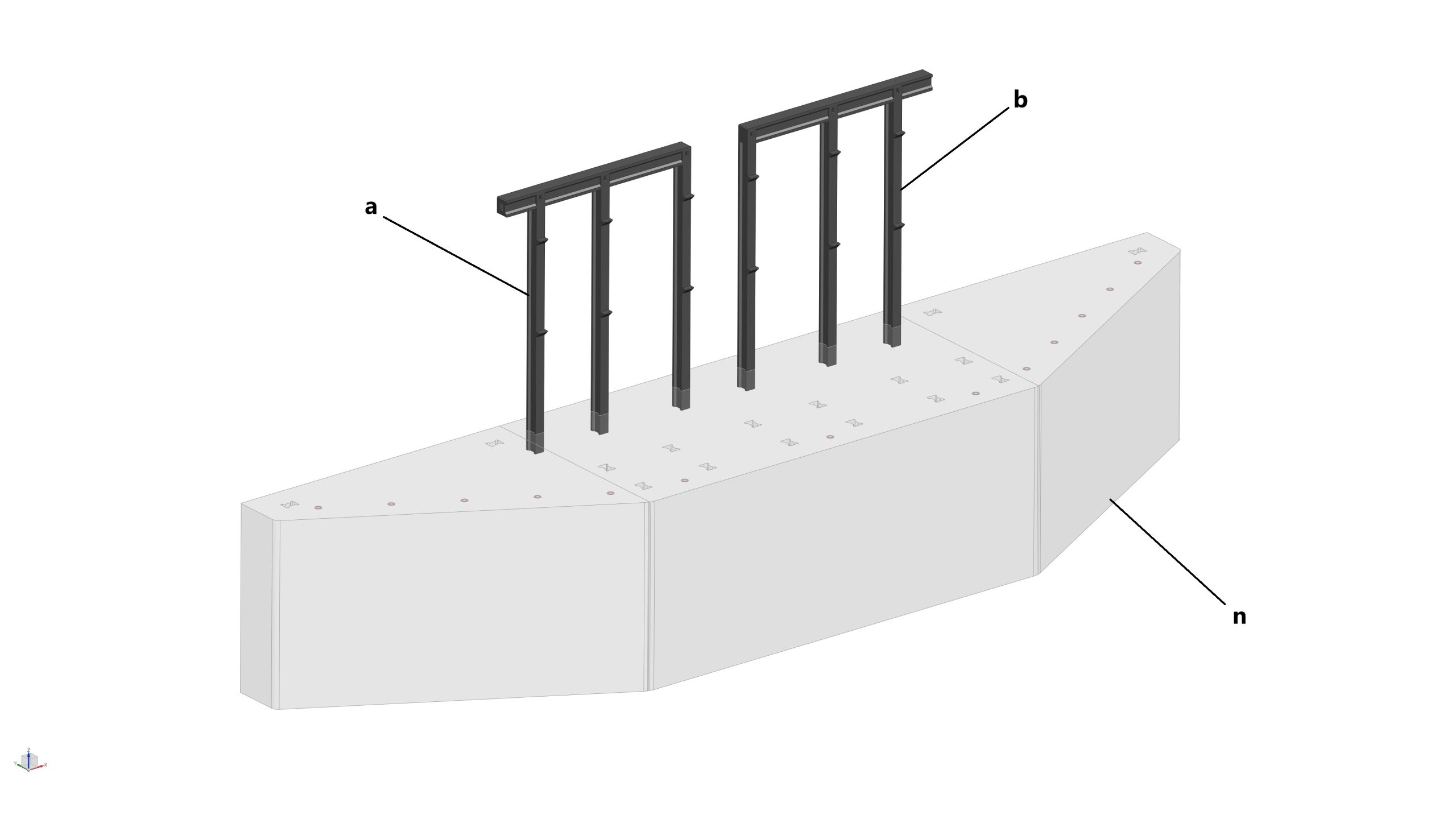
- 1x GSE Bunker Foundation from STEP 11 (n)
- 12x Magnets (3mm dia x 2mm thick) (highlighted in red)
Assembly process
- STEP 12a: Glue 4x magnets (3mm dia x 2mm thick) into their pockets on the side (x2) and top (x2) faces of the GSE Bunker 1st Floor
- STEP 12b: Glue 2x magnets (3mm dia x 2mm thick) into their pockets on the side of the GSE Bunker 2nd Floor
- STEP 12c: Glue 1x magnet (3mm dia x 2mm thick) into the pocket at the bottom of each Short Stair, then glue the Short Railings to the Stairs
- STEP 12d: Glue 2x magnets (3mm dia x 2mm thick) into the pocket at the side of each Long Stair, then glue the Long Railings to the Stairs
- STEP 12e: Insert Beam A’s (LH & RH) to the GSE Bunker Foundation
- STEP 12f: Insert Beam C’s to the GSE Bunker Foundation
- STEP 12g: Insert GSE Bunker 1st Floor to the gantry
- STEP 12h: Insert GSE Bunker 2nd Floor to the gantry
- STEP 12i: Insert Beam B’s (LH & RH) to the GSE Bunker Foundation
- STEP 12j: Install 2x Short Stairs to the gantry
- STEP 12k: Install 2x Long Stairs (LH & RH) to the gantry
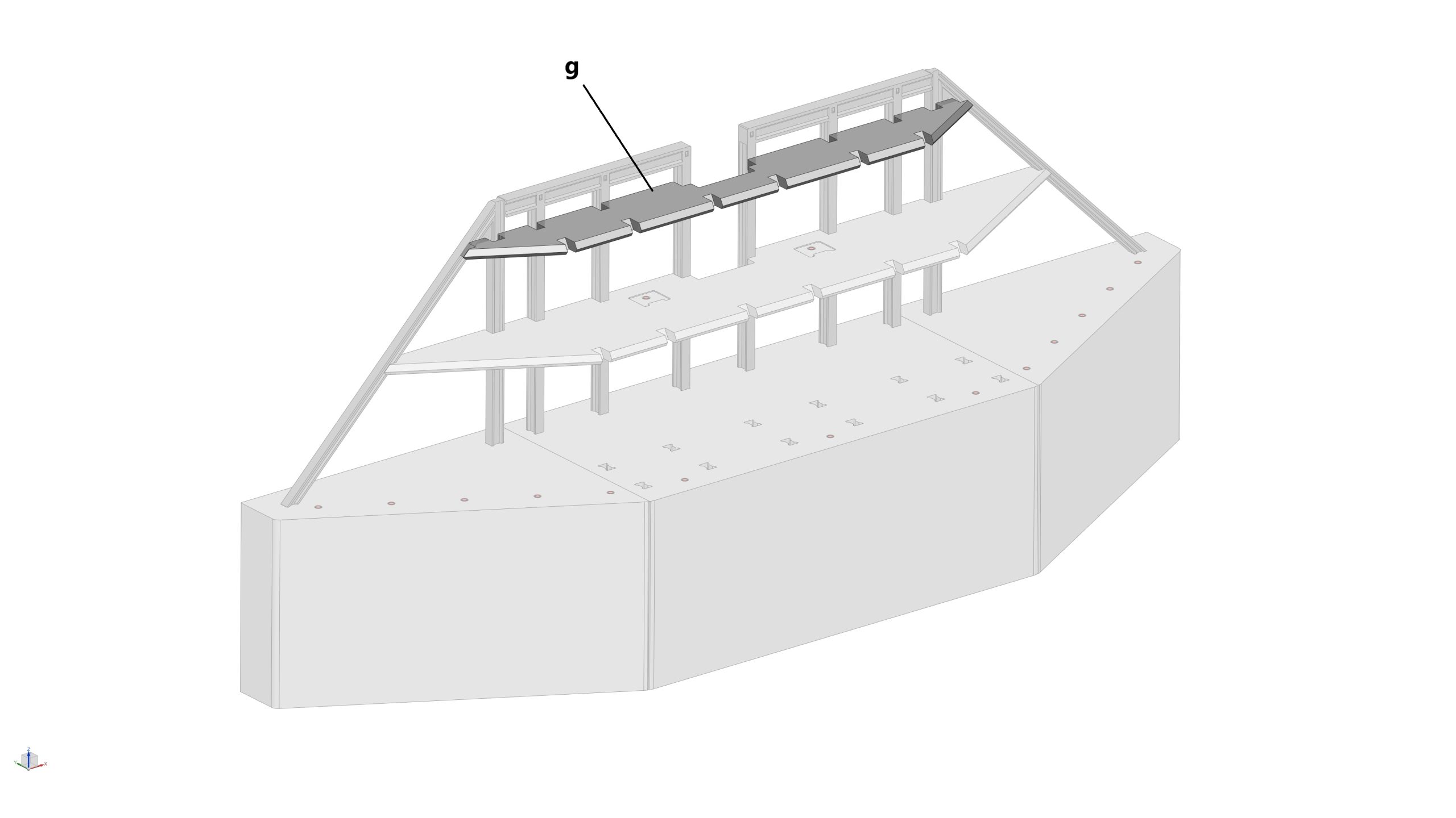
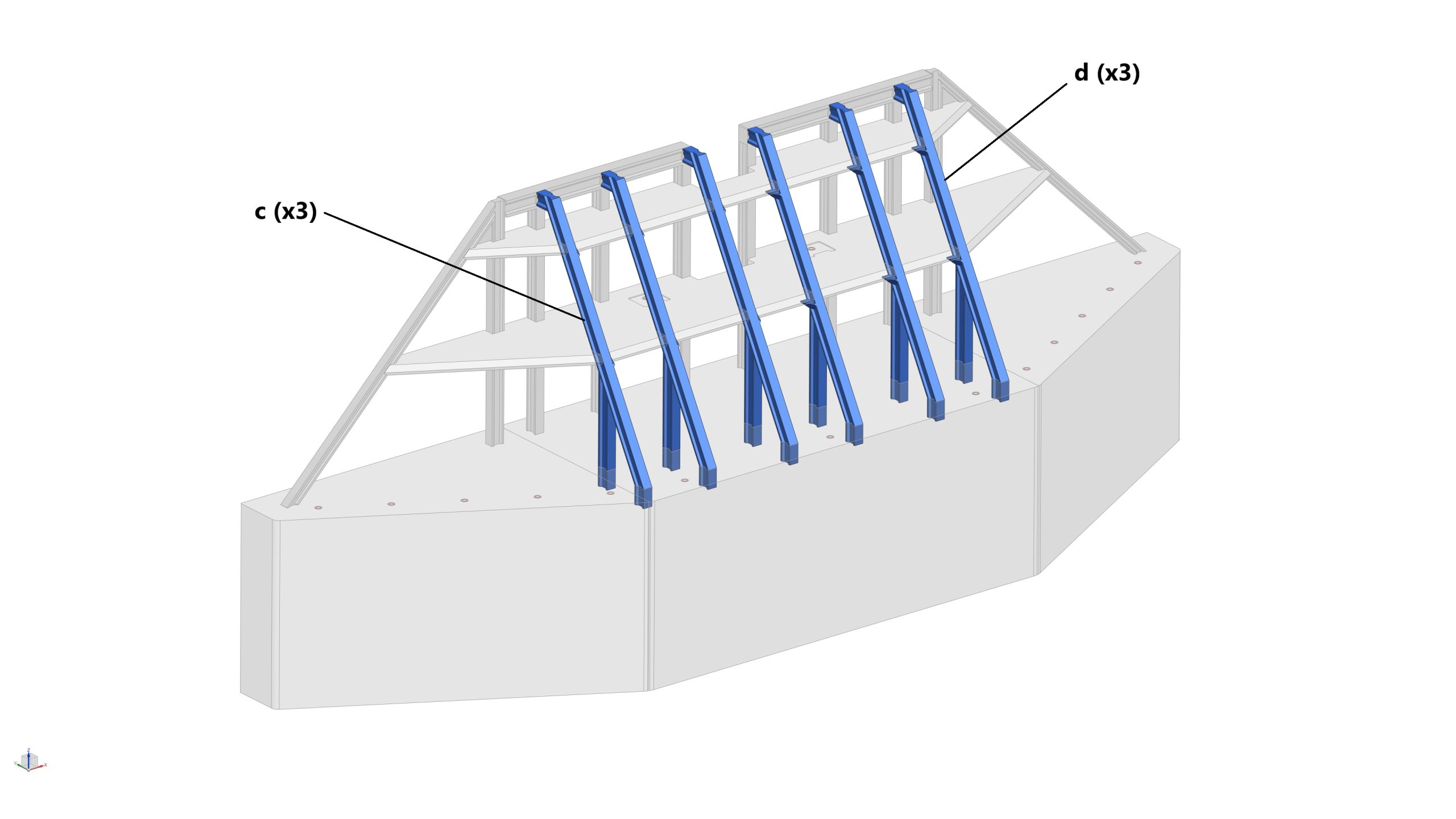
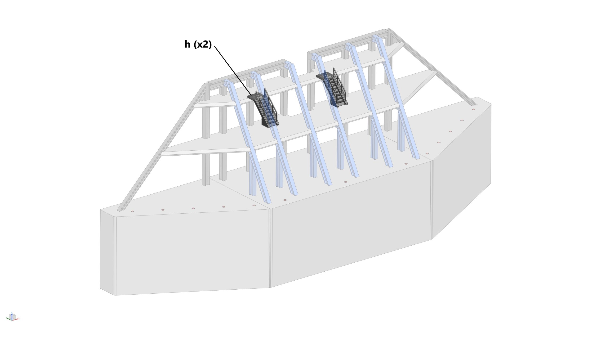
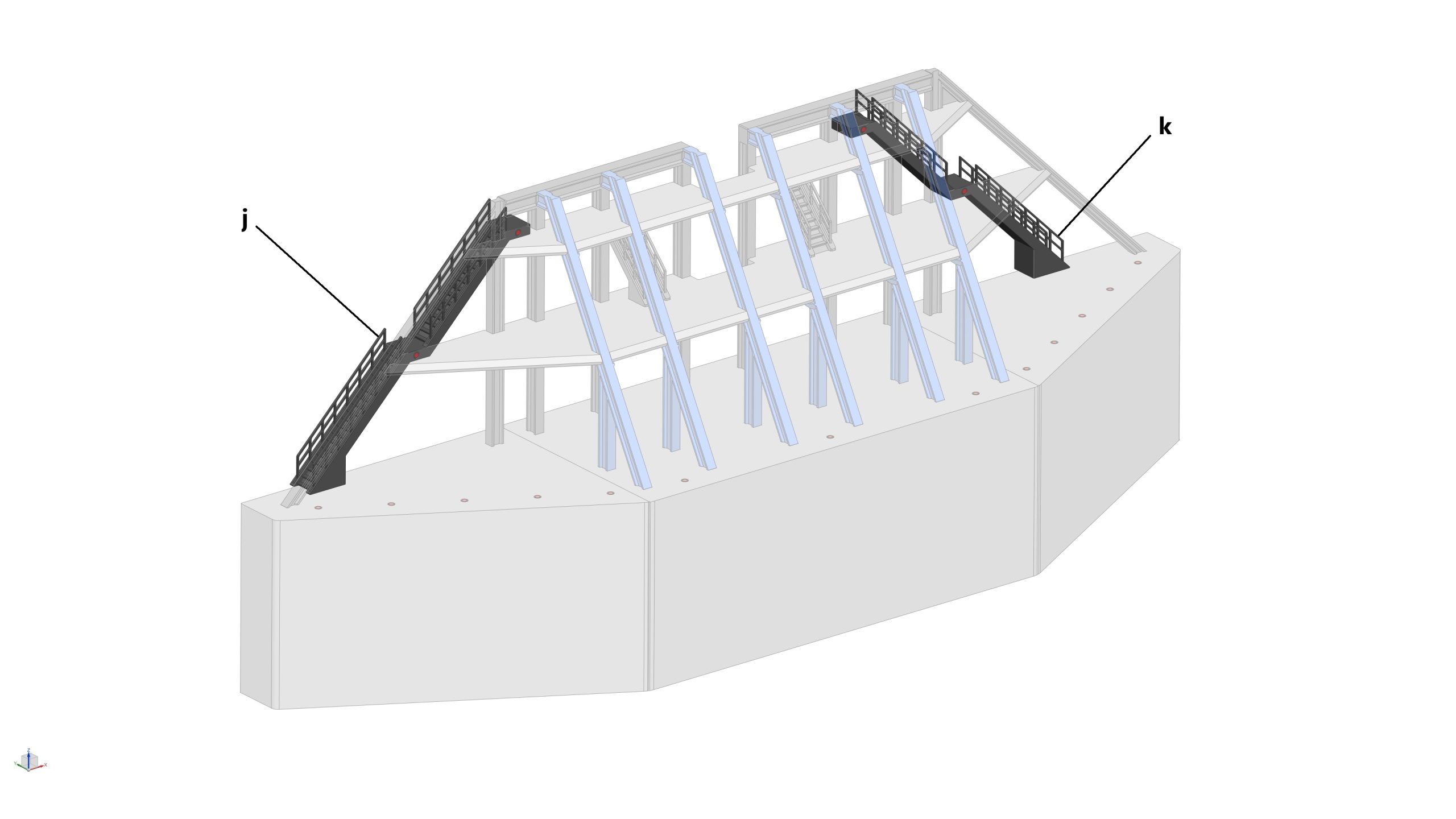
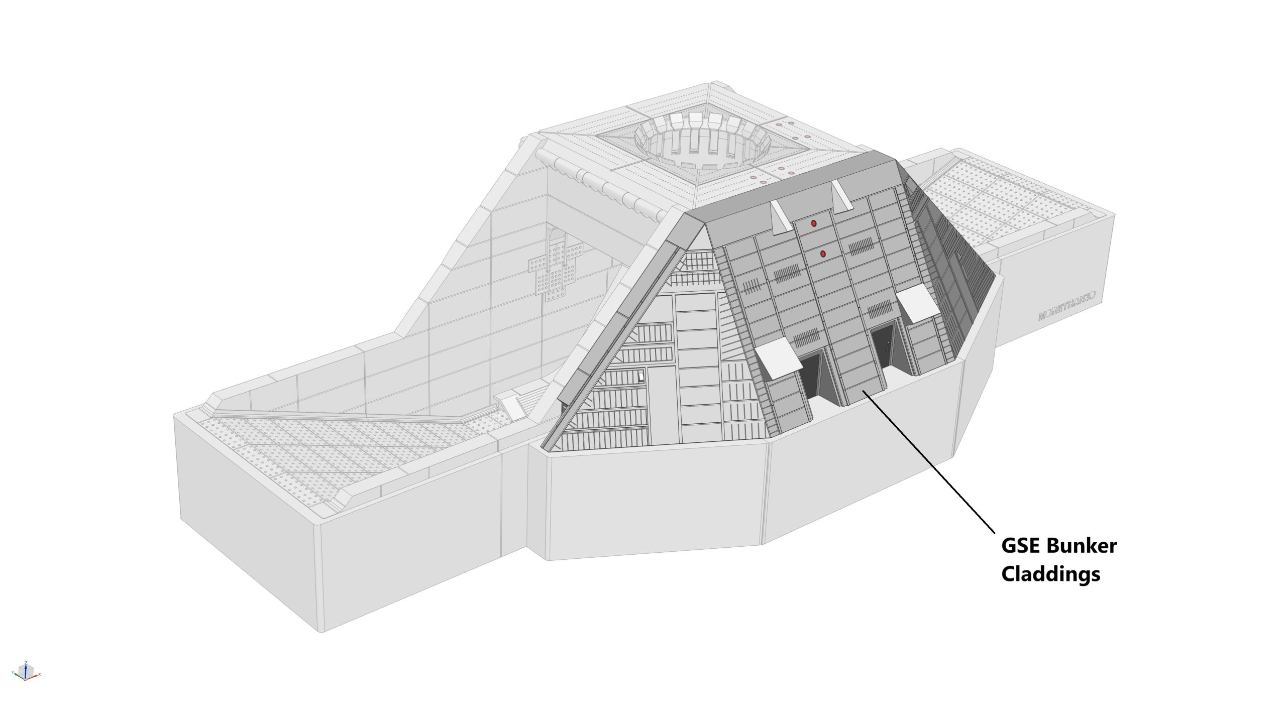
STEP 13: Assemble the GSE Bunker Cladding
Parts required (refer to the photos below)
- 1x GSE Bunker Cladding (LH) (a)
- 1x GSE Bunker Cladding (Center) (b)
- 1x GSE Bunker Cladding (RH) (c)
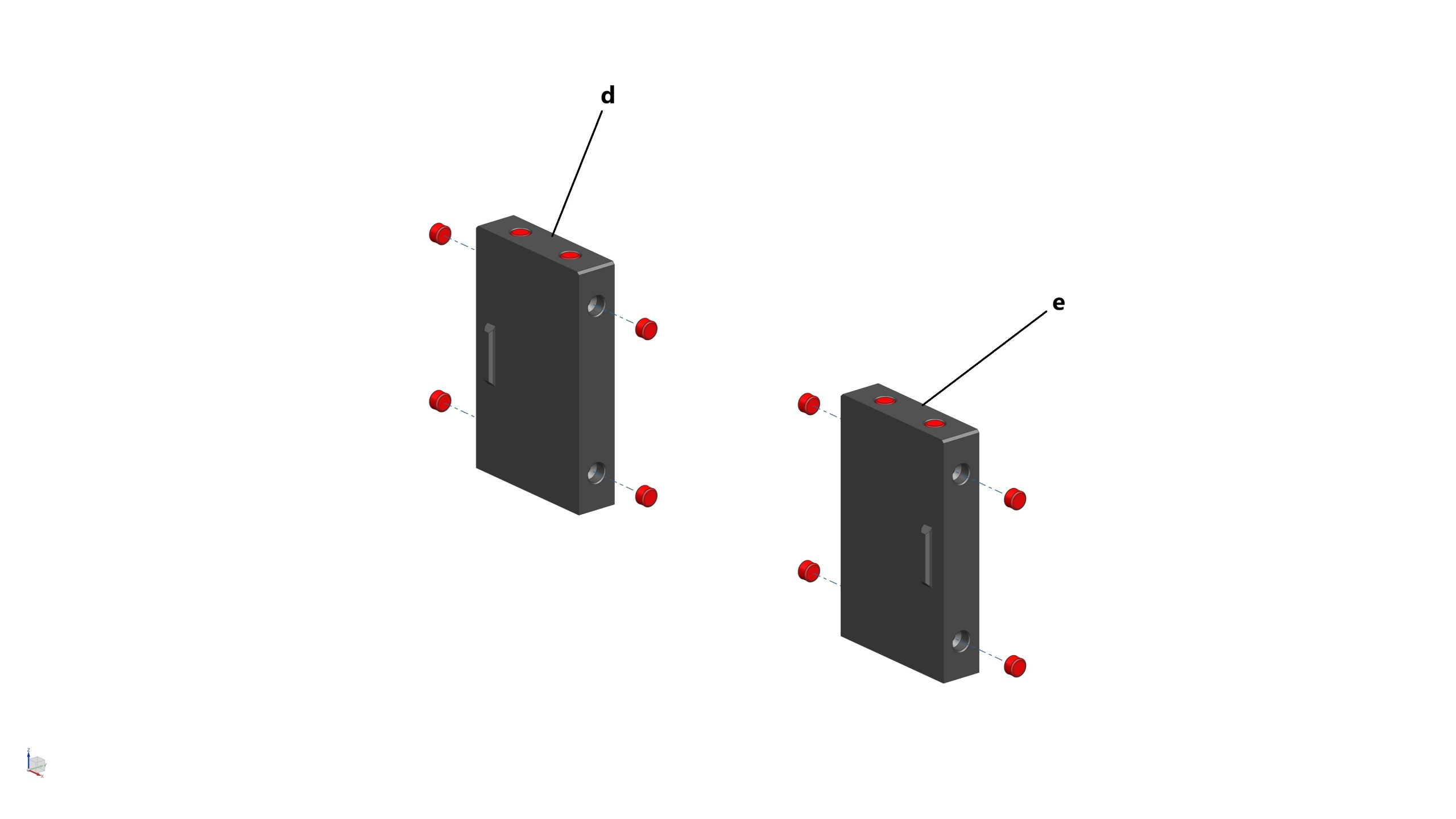
- 1x Main Access Door (LH) (d)
- 1x Main Access Door (RH) (e)
- 47x Magnet (3mm dia x 2mm thick) (highlighted in red)
- 2x Magnet (5mm dia x 3mm thick) (highlighted in red)
Assembly process
- STEP 13a: Glue 10x magnets (3mm dia x 2mm thick) into their pockets on the side (x5) and bottom (x5) faces of the GSE Bunker Cladding (LH)
- STEP 13b: Glue 15x magnets (3mm dia x 2mm thick) into their pockets on the bottom face (x3), and around the walls of the Main Access Doors (x12) of the GSE Bunker Cladding (Centre). Then glue 2x magnets (5mm dia x 3mm thick) into their pockets on the front face of the GSE Bunker Cladding (Centre)
- STEP 13c: Glue 10x magnets (3mm dia x 2mm thick) into their pockets on the side (x5) and bottom (x5) faces of the GSE Bunker Cladding (RH)
- STEP 13d: Glue 12x magnets (3mm dia x 2mm thick) into their pockets around the walls of the Main Access Doors (LH & RH)
- STEP 13e: Install the Main Access Doors (LH & RH) to the GSE Bunker Cladding (Centre)
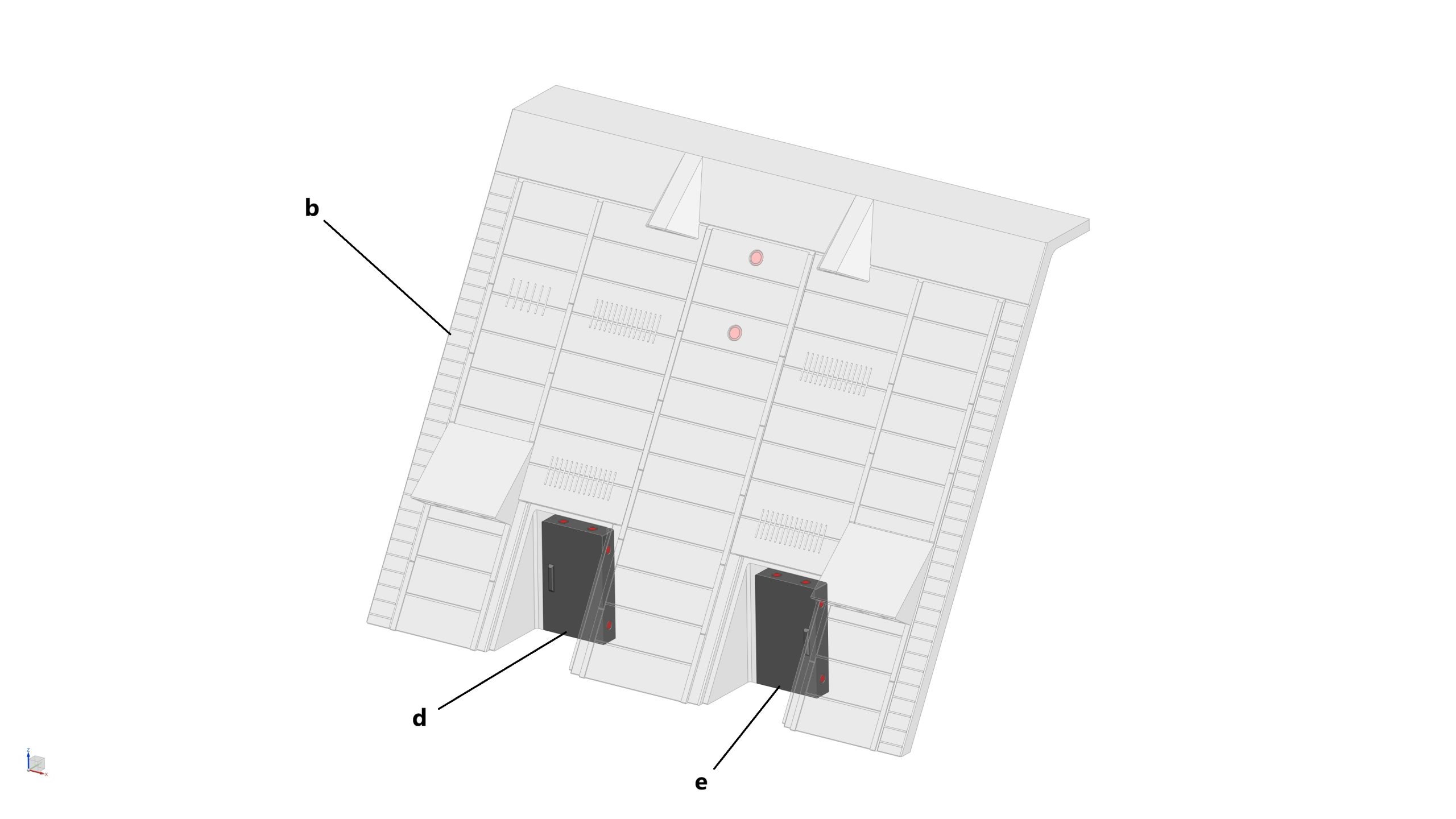
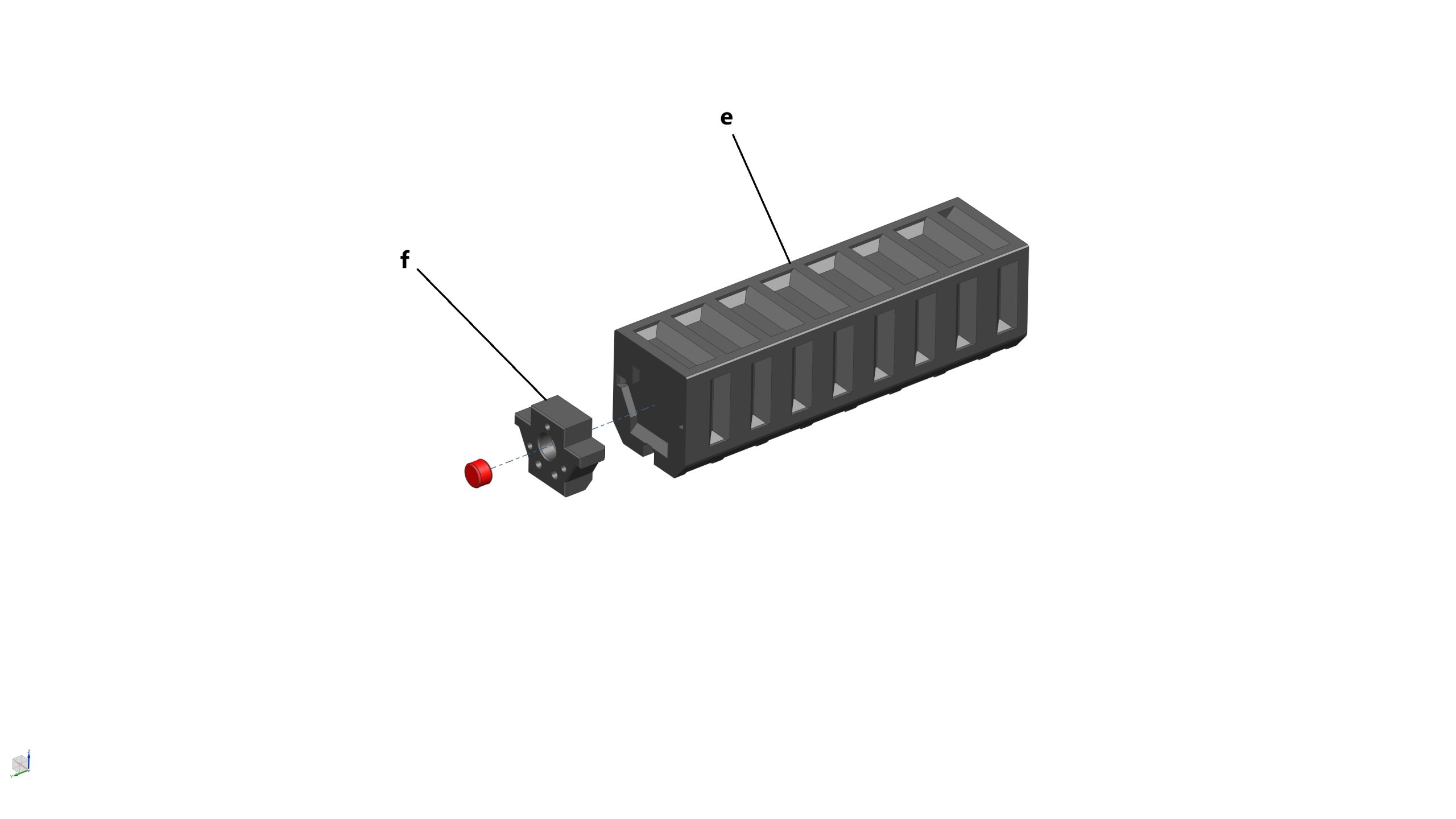
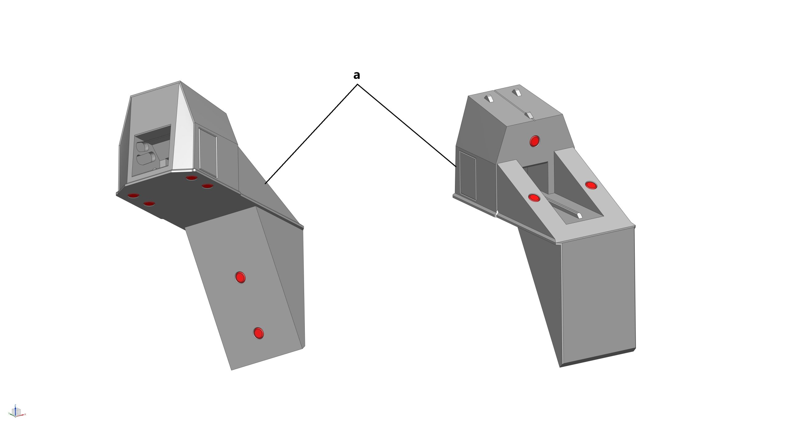
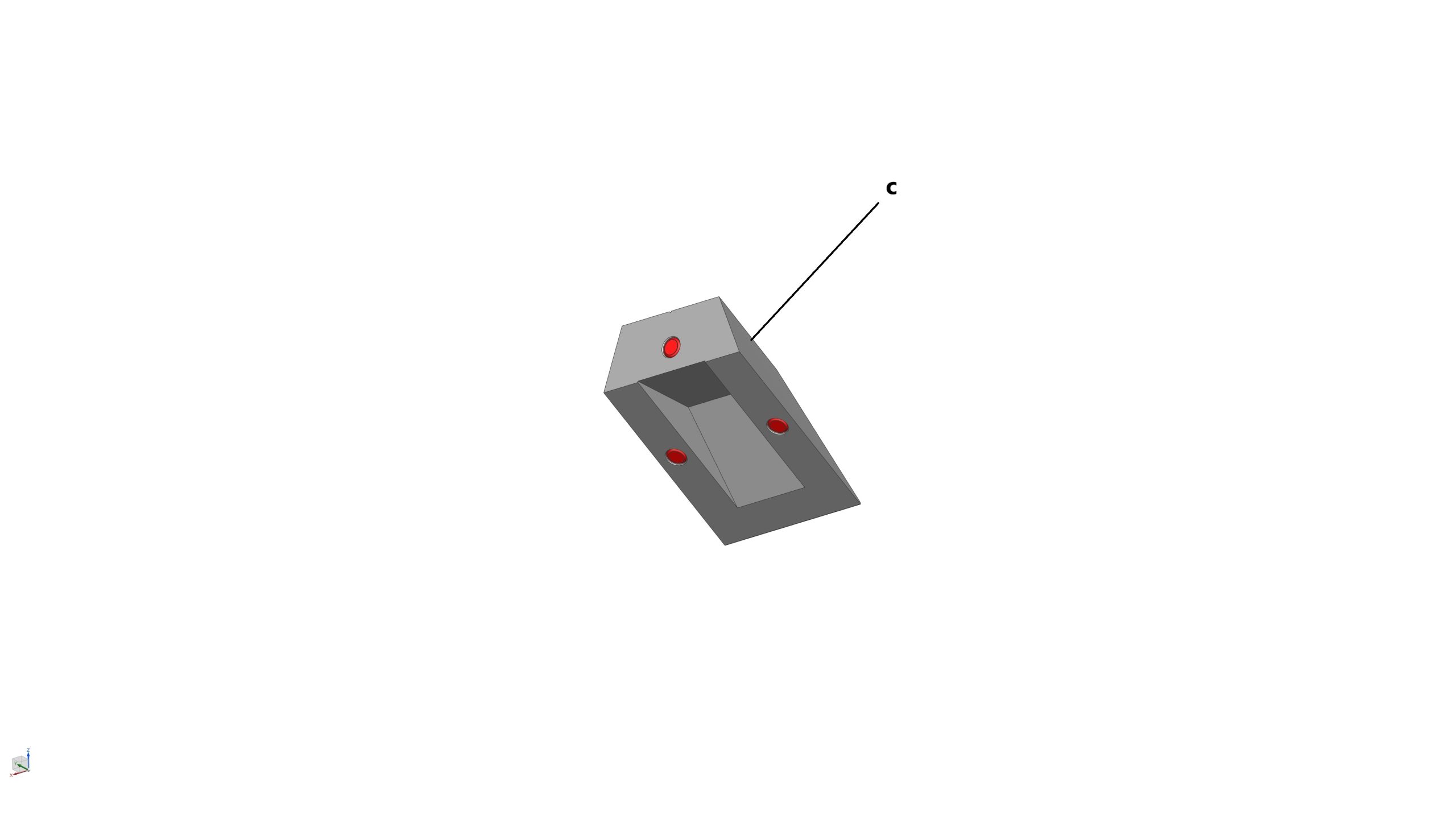
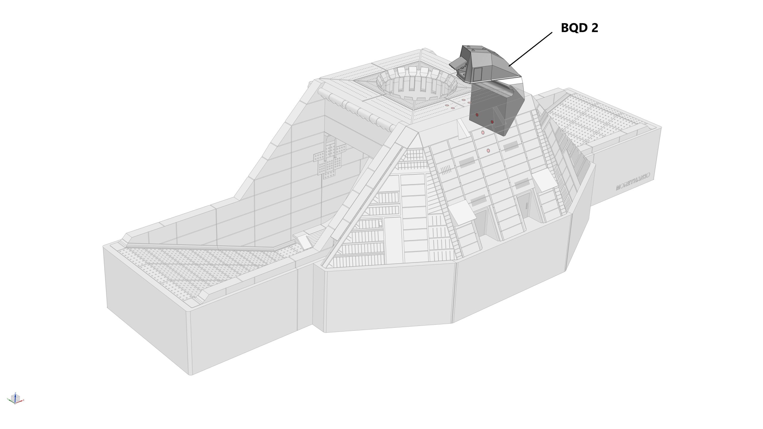
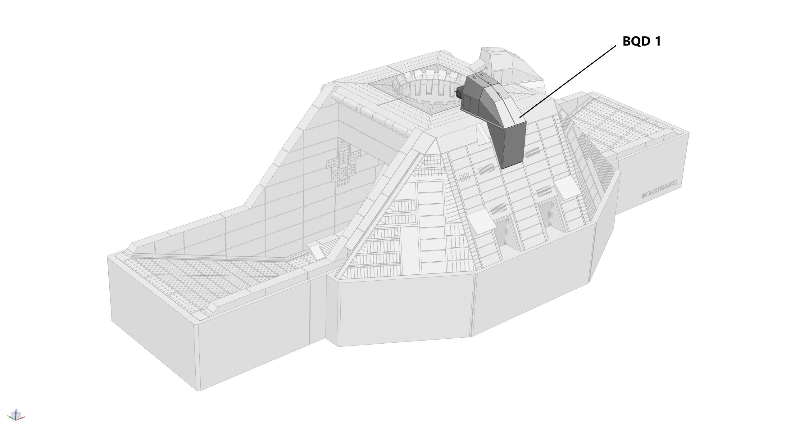
STEP 14: Assemble the Booster Quick Disconnect (BQD)
Parts required (refer to the photos below)
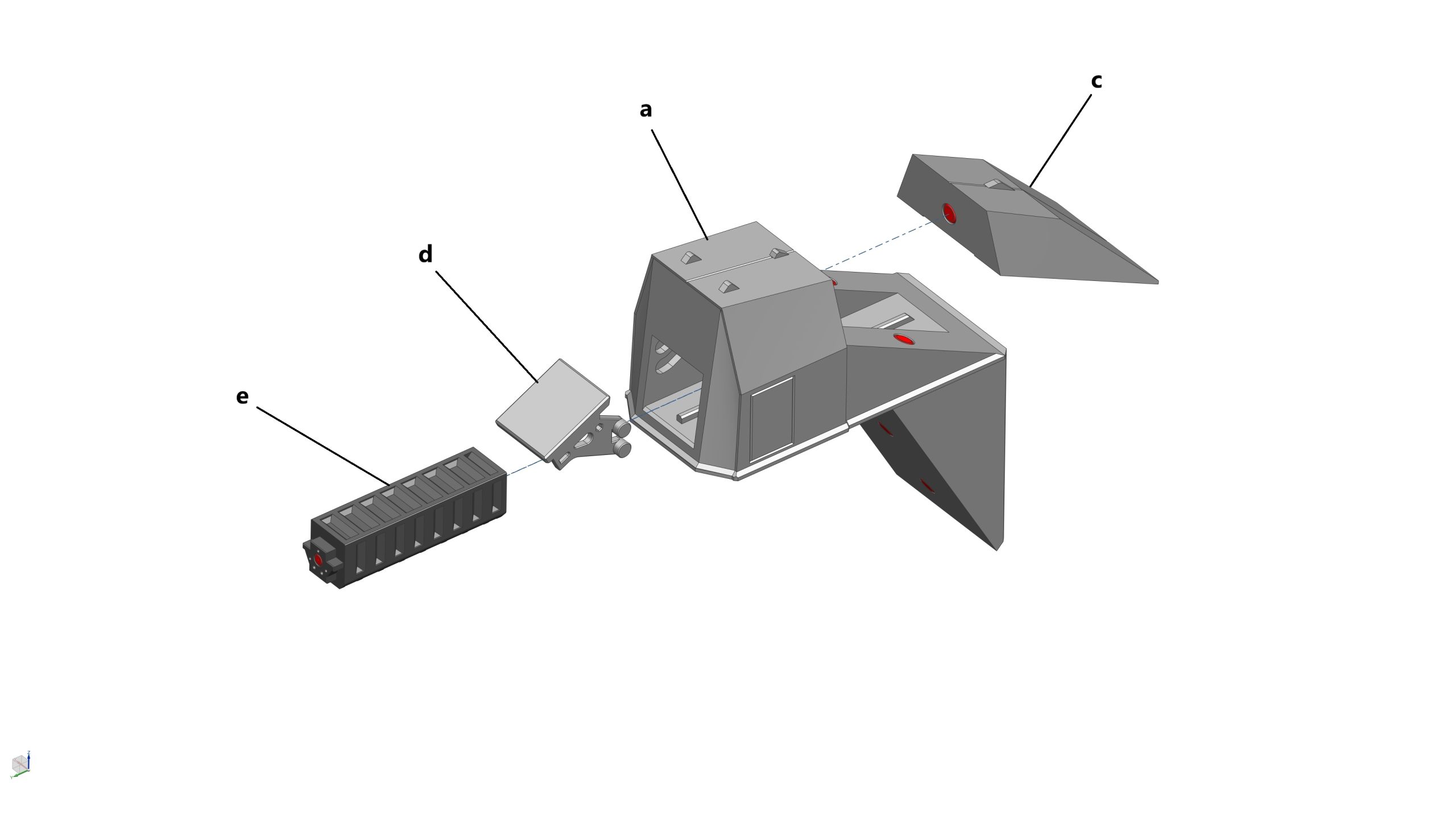
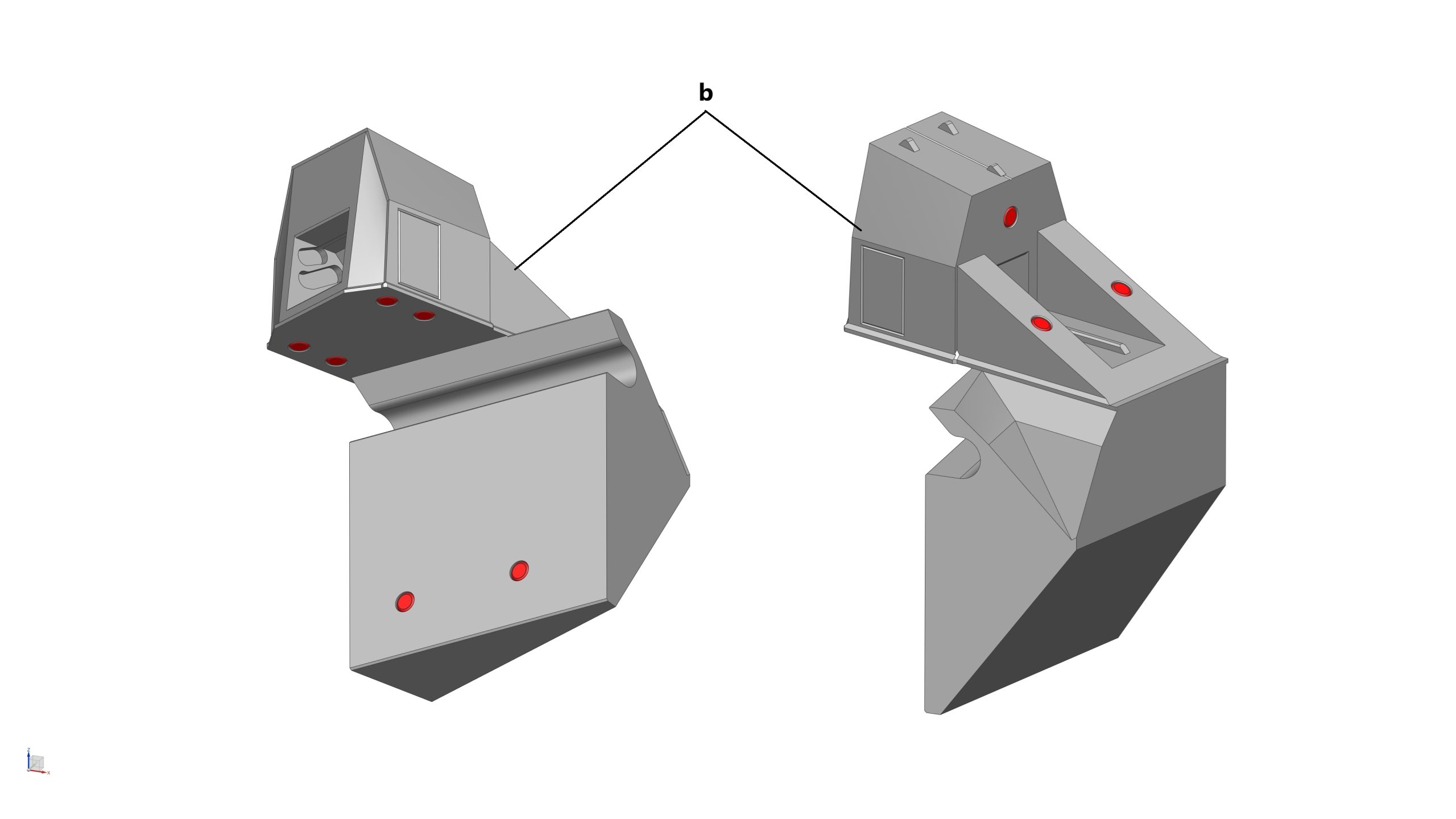
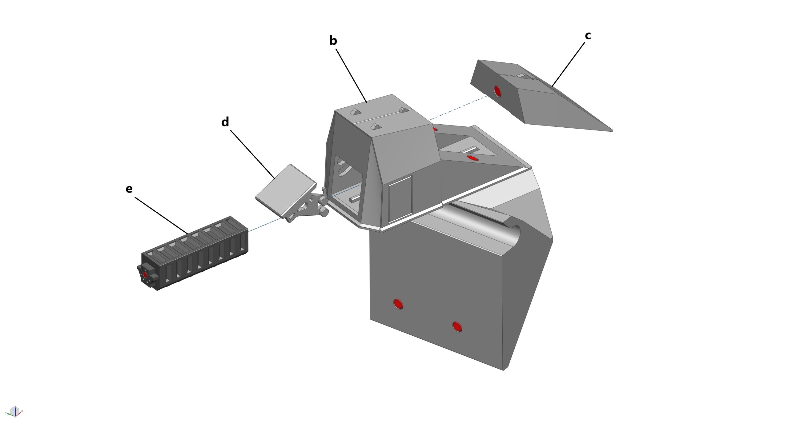
- 1x BQD1 (a)
- 1x BQD2 (b)
- 2x BQD (Top) (c)
- 2x BQD Door (d)
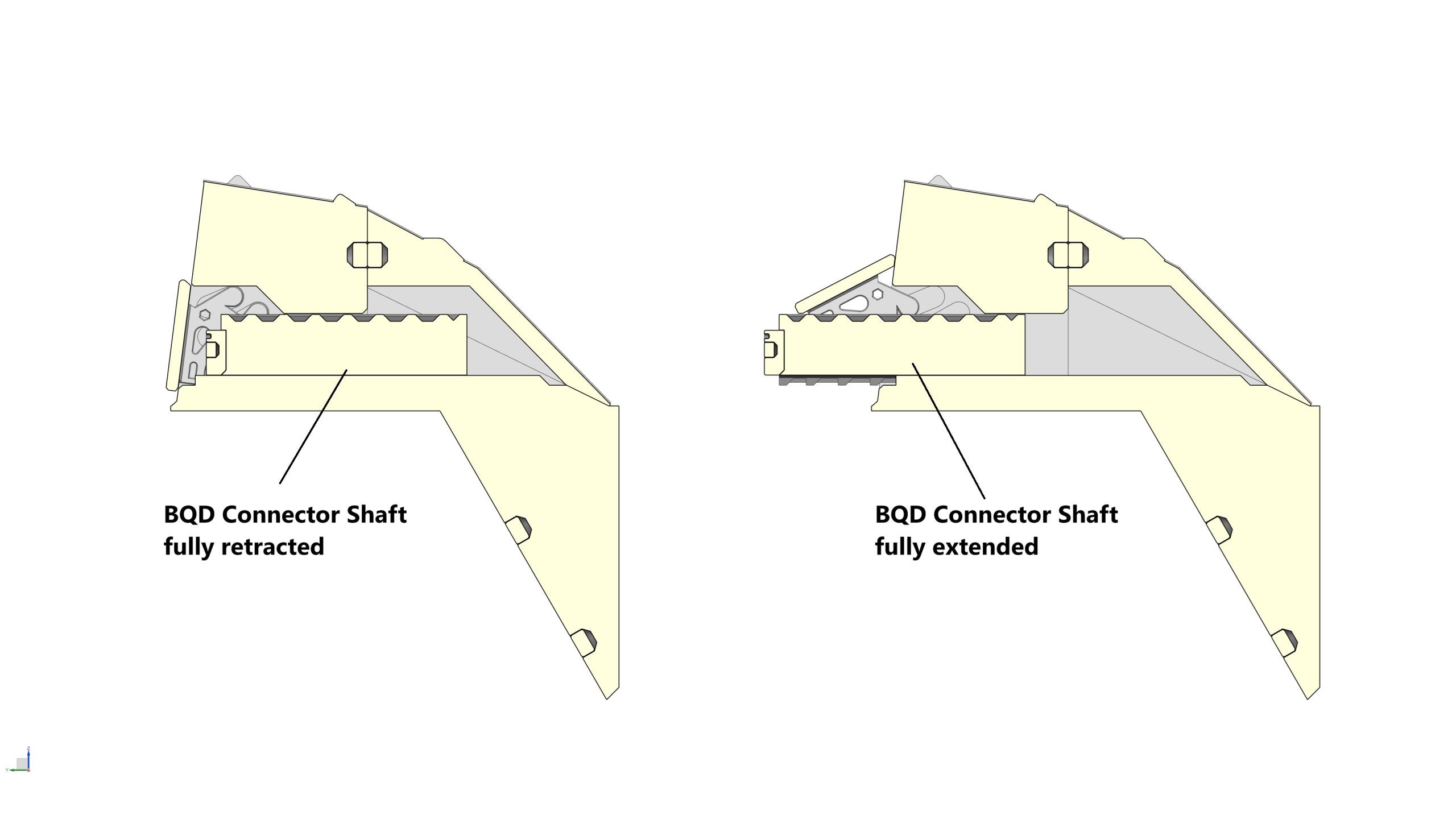
- 2x BQD Connector Shaft (e)
- 2x BQD Connector Plate (f)
- 2x Magnet (3mm dia x 2mm thick) (highlighted in red)
- 24x Magnet (5mm dia x 3mm thick) (highlighted in red)
Assembly process
- STEP 14a: Glue 1x magnet (3mm dia x 2mm thick) into the pocket on the BQD Connector Plate, then glue the BQD Connector Plate to the BQD Connector Shaft
- STEP 14b: Glue 9x magnet (5mm dia x 3mm thick) into the pockets at the back (x3) and bottom (x6) sides the BQD1
- STEP 14c: Glue 3x magnet (5mm dia x 3mm thick) into the pockets on the BQD (Top)
IMPORTANT: DO NOT glue the BQD (Top) to the BQD body – this part needs to be removable in order to provide access to push the BQD Connector Shaft in/out of the BQD
- STEP 14d: Assemble the BQD1
- STEP 14e: Glue 9x magnet (5mm dia x 3mm thick) into the pockets at the back (x3) and bottom (x6) sides the BQD2
- STEP 14f: Assemble the BQD2
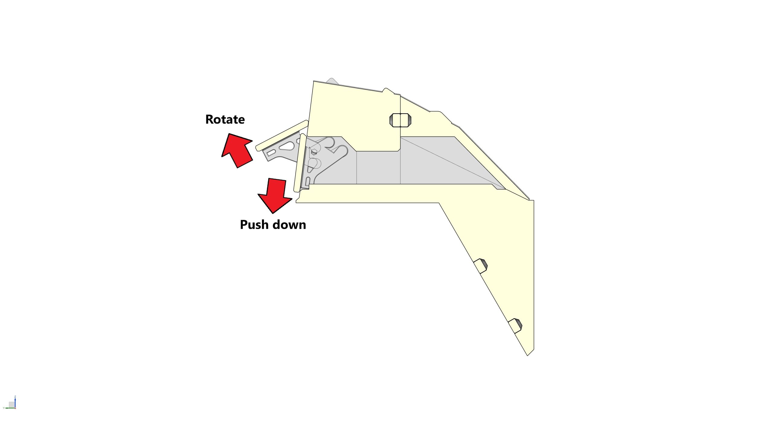
- STEP 14g: Test the BQD by opening/closing the Door. Please note: to open the door, you need to push it down slightly and rotate upwards simultaneously
- STEP 14h: Test the BQD Connector Shaft by removing the BQD (Top), and push the BQD Connector Shaft forward with your finger. The BQD Connector Shaft should extend without catching on the BQD Door
STEP 15: Assemble Pad 2 model
Parts required (refer to the photos below)
- All parts & sub-assemblies from STEP 2 to STEP 14
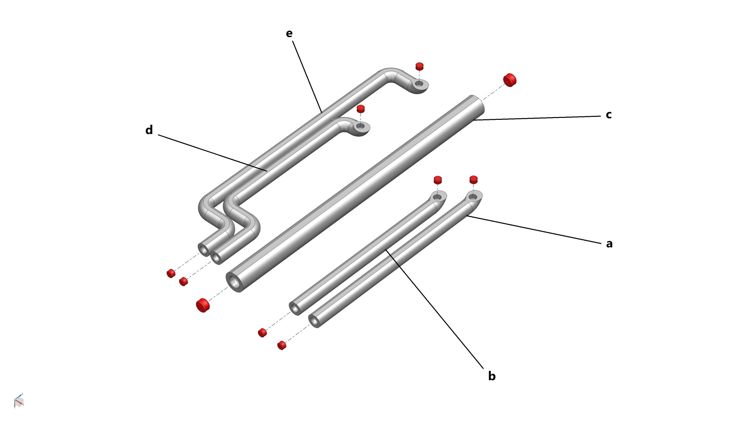
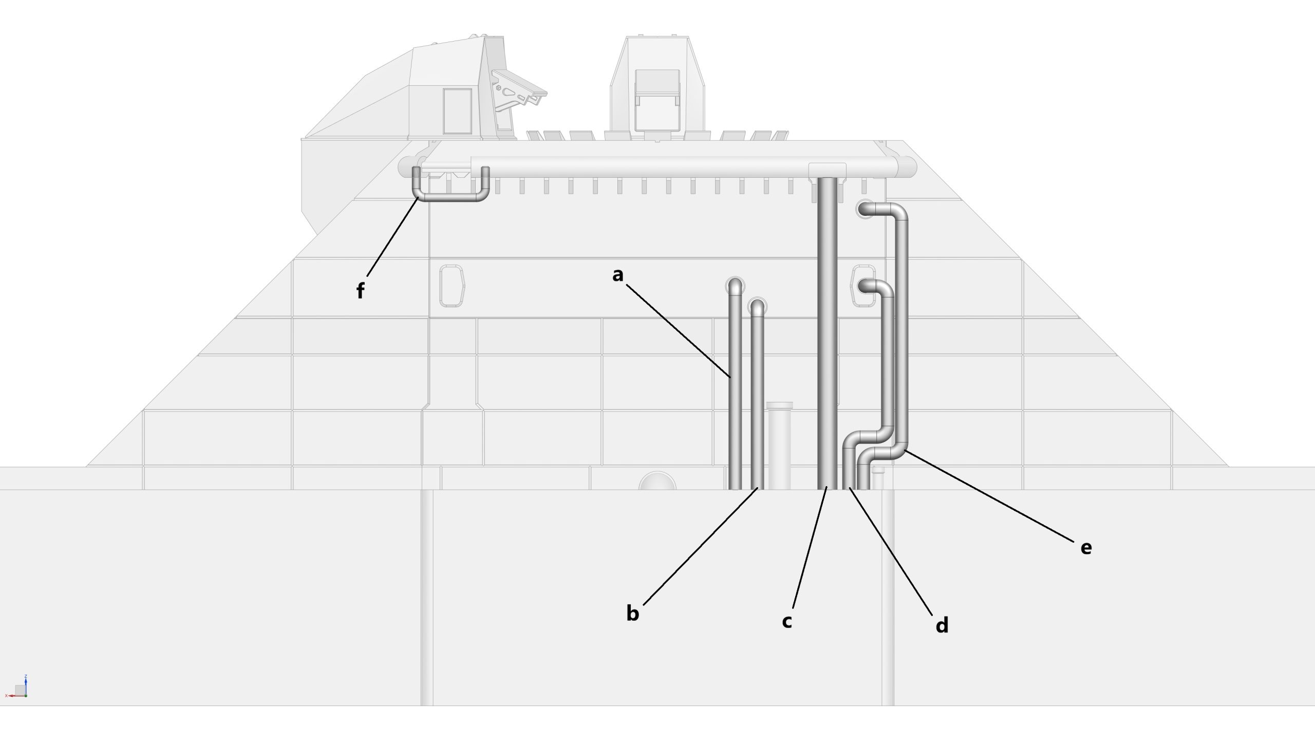
- 1x Pipe 1 (a)
- 1x Pipe 2 (b)
- 1x Pipe 3 (c)
- 1x Pipe 4 (d)
- 1x Pipe 5 (e)
- 1x Top Deck U-Shaped Pipe (f)
- 8x Magnet (3mm dia x 2mm thick) (highlighted in red)
- 2x Magnet (5mm dia x 3mm thick) (highlighted in red)
Assembly process
- STEP 15a: Install the Top Deck to the Trench
- STEP 15b: Install the GSE Bunker Gantry/Foundation to the Trench
- STEP 15c: Install the GSE Bunker Claddings over the Gantry
- STEP 15d: Install the BQD2 to the Top Deck
- STEP 15e: Install the BQD1 to the Top Deck
- STEP 15f: Glue 8x magnet (3mm dia x 2mm thick) into the pockets at the ends of Pipe 1,2,4,5. Glue 2x magnet (5mm dia x 3mm thick) into the pockets at the ends of Pipe 3
- STEP 15g: Install Pipes 1,2,3,4,5, and the Top Deck U-Shaped Pipe to the back of the Pad 2.
STEP 16: Install the BOOSTER-S8 to Pad 2
Parts required (refer to the photos below)
- 1x Pad 2 from STEP 15
- 1x Turning Tool from STEP 9
- 1x BOOSTER-S8
Assembly process
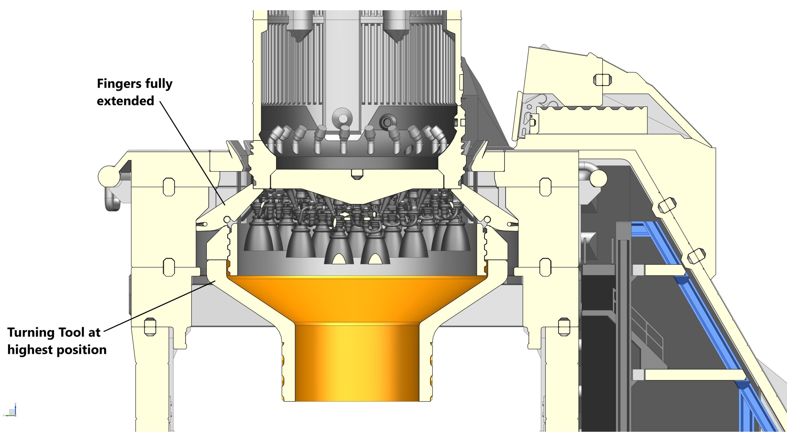
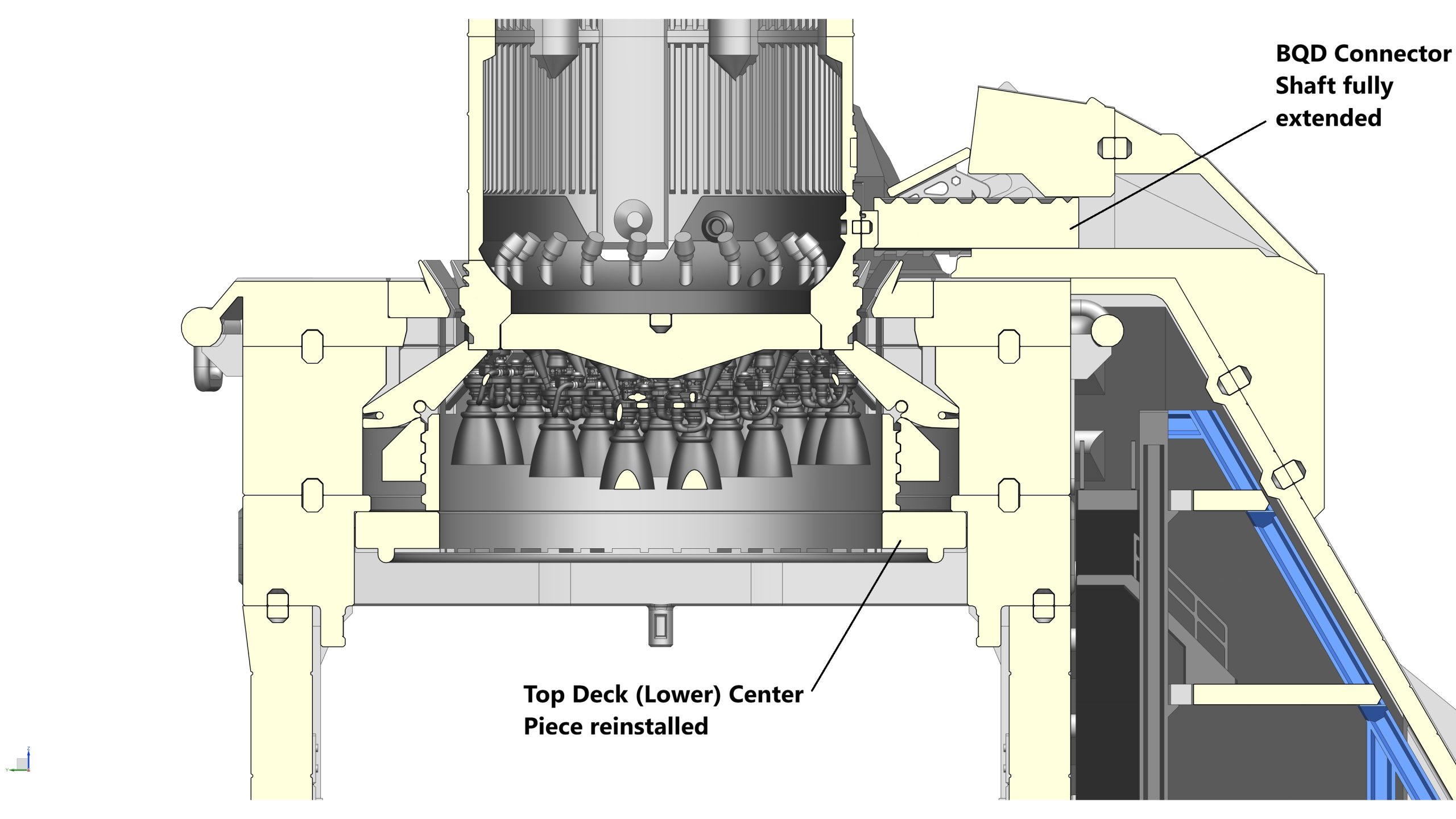
- STEP 16a: Remove the Top Deck (Lower) Center Piece under the Top Deck
- STEP 16b: Insert the Turning Tool from under the Top Deck, ensure that the Tool is engaged with the Threaded Ring
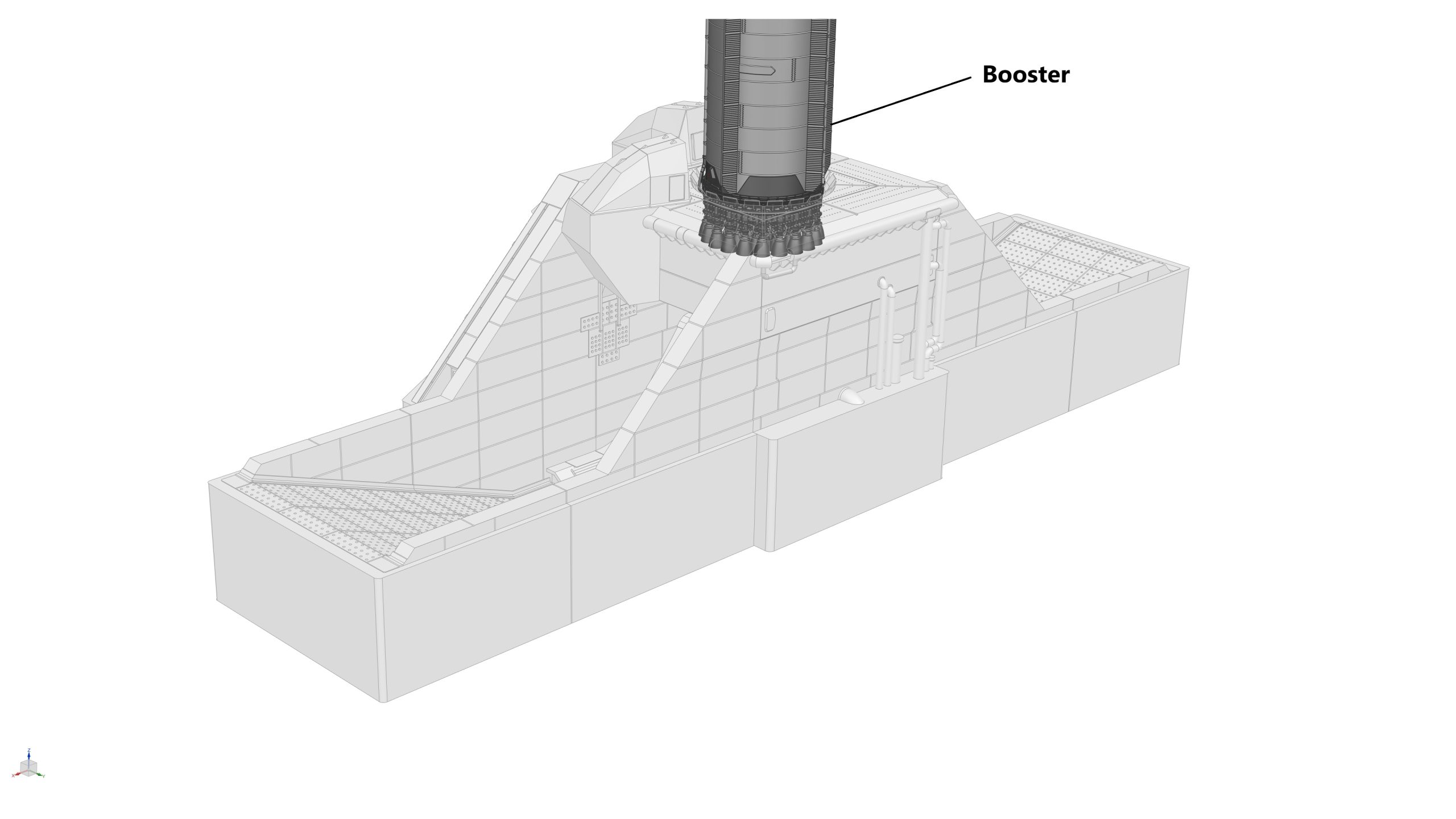
- STEP 16c: Carefully lower the Booster into the Top Deck until it reaches approximately the correct height (the two BQD plates of the Booster are aligned with the doors of the two BQD’s of the Pad 2)
- STEP 16d: With one hand holding the Booster, rotate the Turning Tool to activate the Clamping System. Ensure all Fingers are fully extended, and the Booster is secured.
- STEP 16e: Push the BQD Connector Shafts forward from both BQD’s until their BQD Connector Plates engaged with those on the Booster. Remove the Turning Tool, and reinstall the Top Deck (Lower) Center Piece
- To remove the Booster from Pad 2, repeat the operations above in reverse
Congratulations, you have fully built the Pad 2-S1 model!