How to Print & Assemble The OLM-S2

How to print the OLM-S2

If you want to save this How-To instruction as a pdf file (and print it out later if needed), simply copy the URL of this page and paste it to https://www.printfriendly.com/ . Printfriendly will generate a printer-friendly pdf of the page with all the texts and images for you.

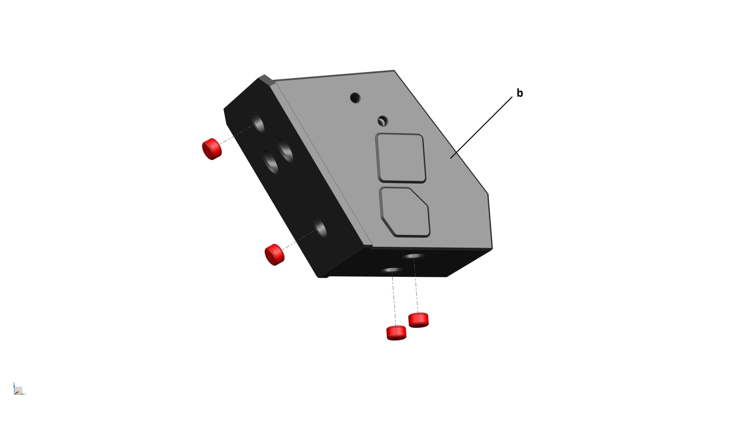
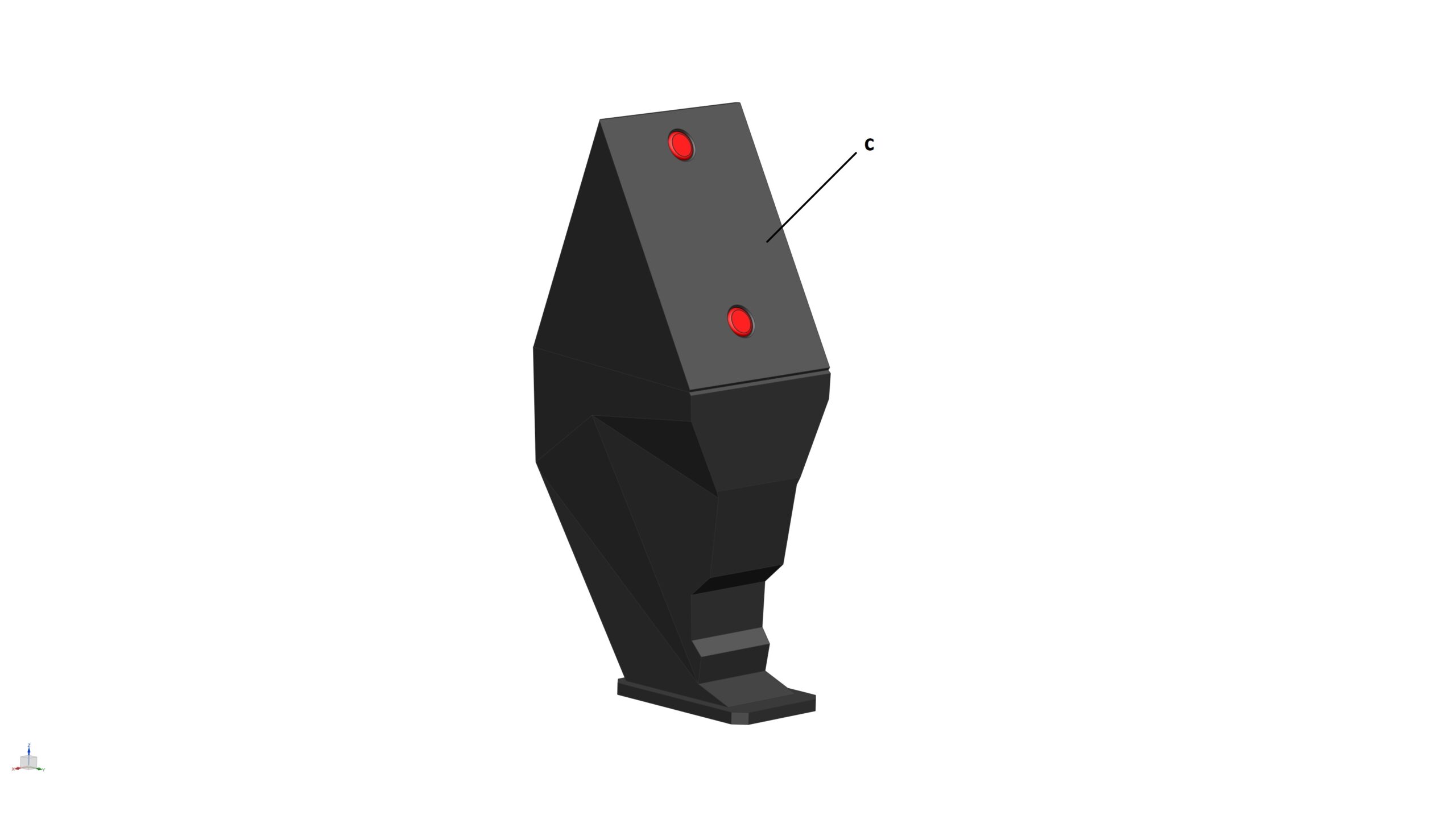
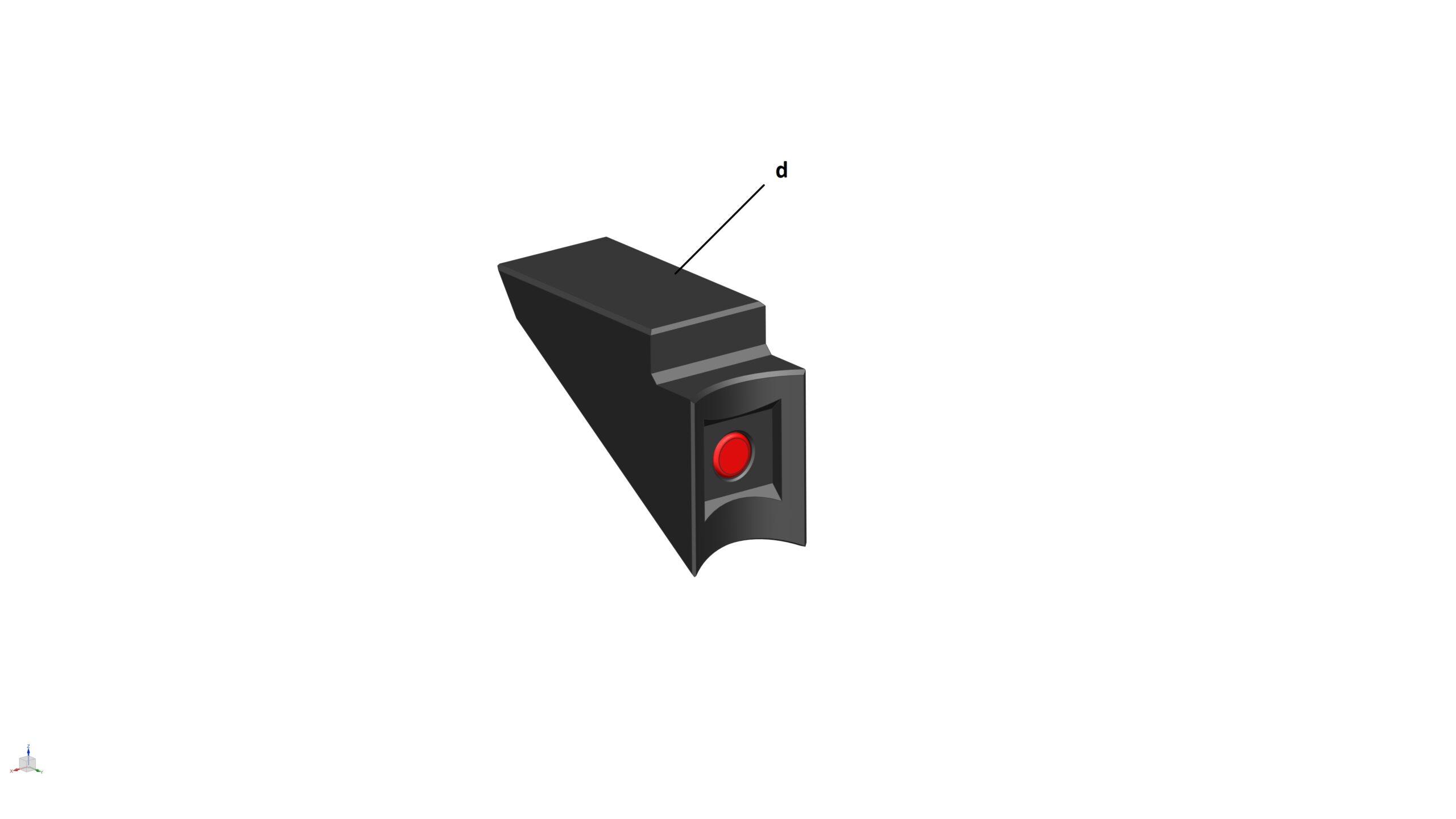
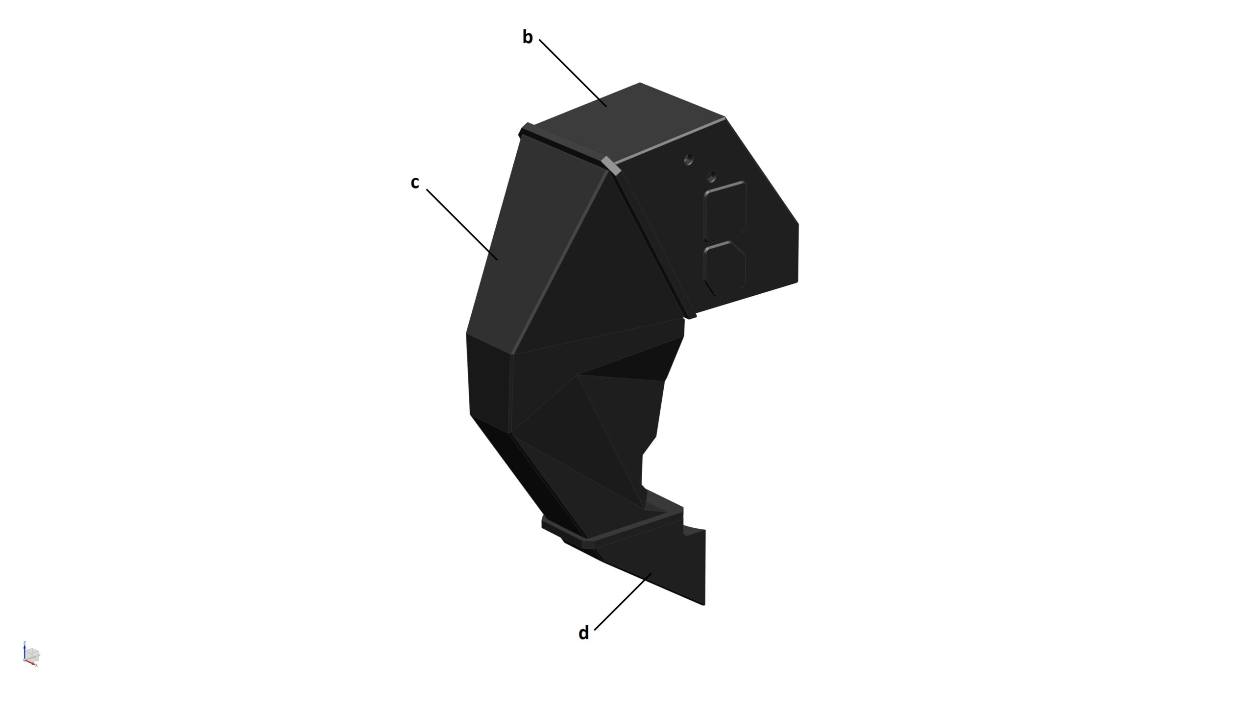
All of the STL files are really straight forward to print. All you need to do is load them into your slicer software (I use Cura), select your desirable settings (e.g. layer height, infill percentage, etc.) and slice the parts. I used 0.4mm nozzle and 0.2mm layer height to print all parts of this model.

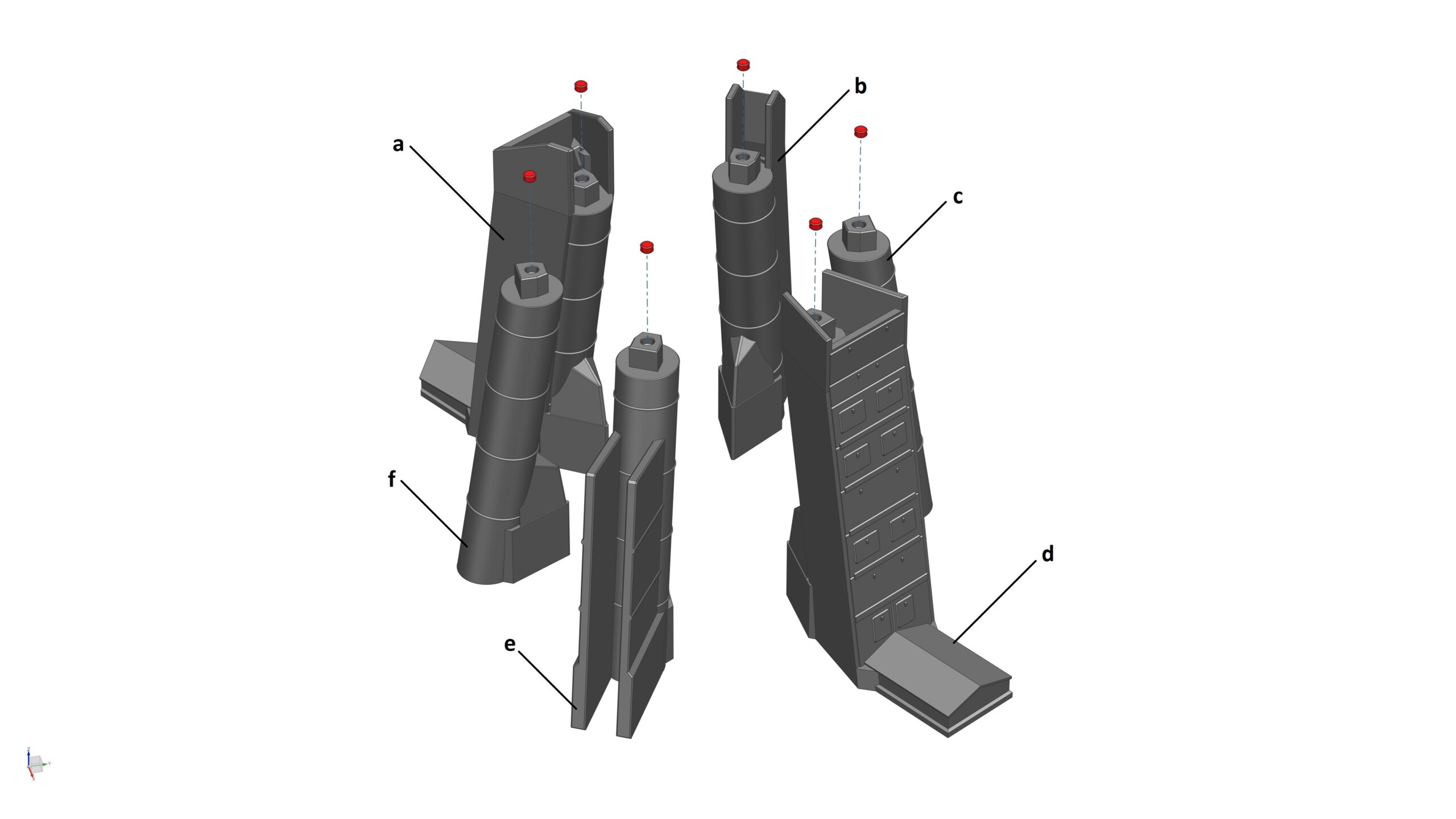
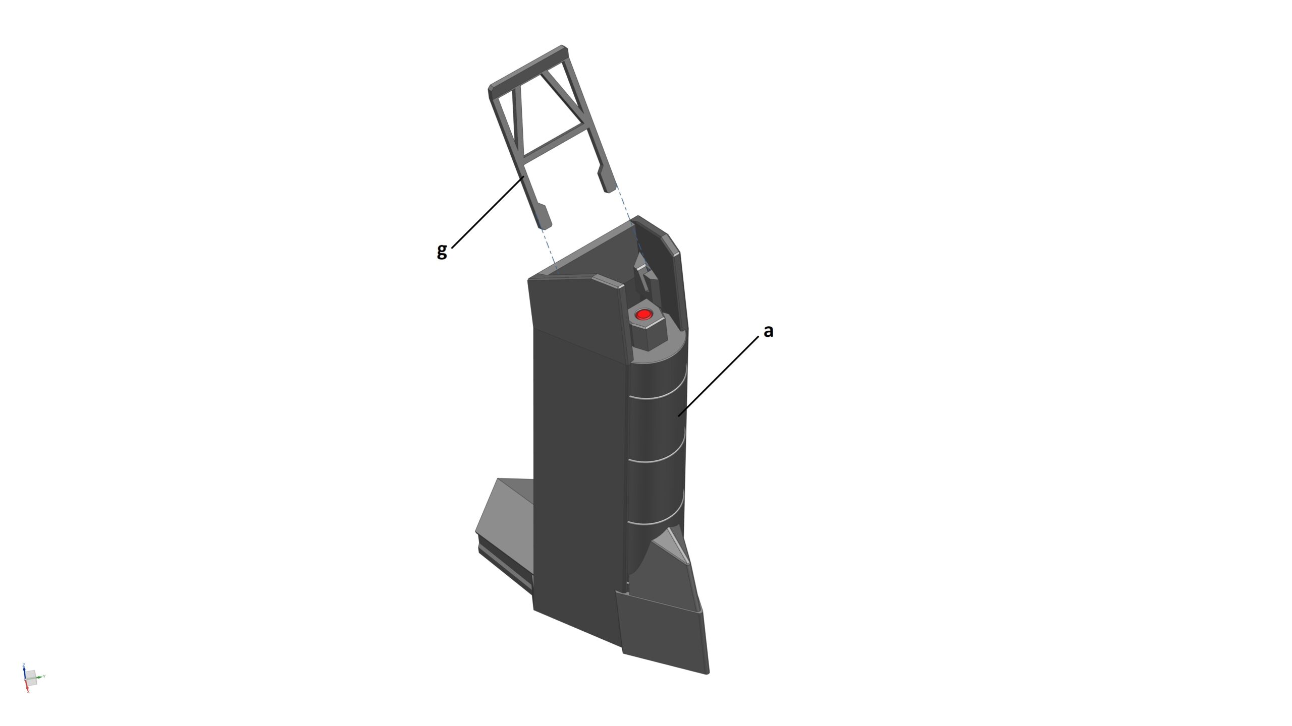
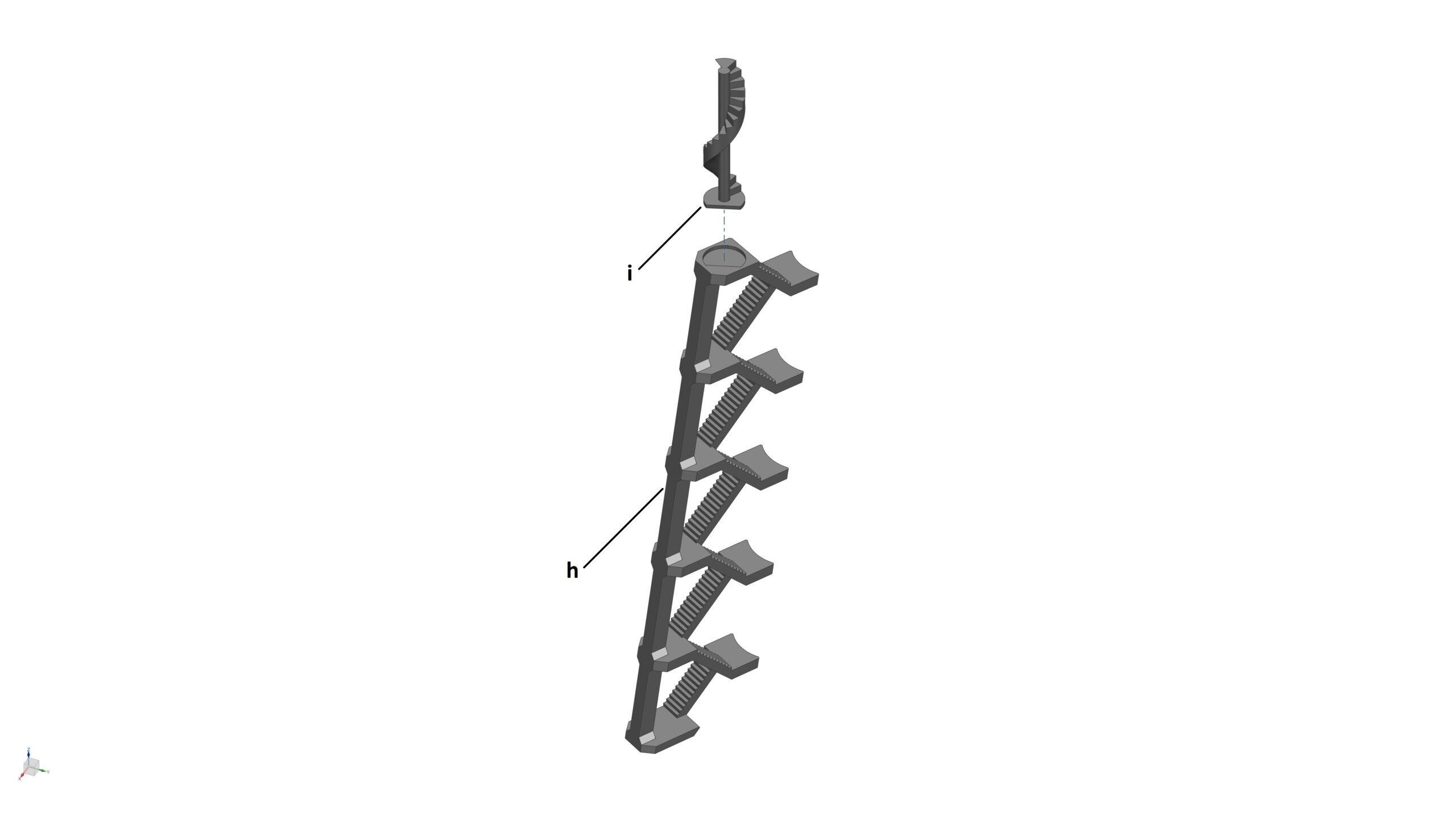
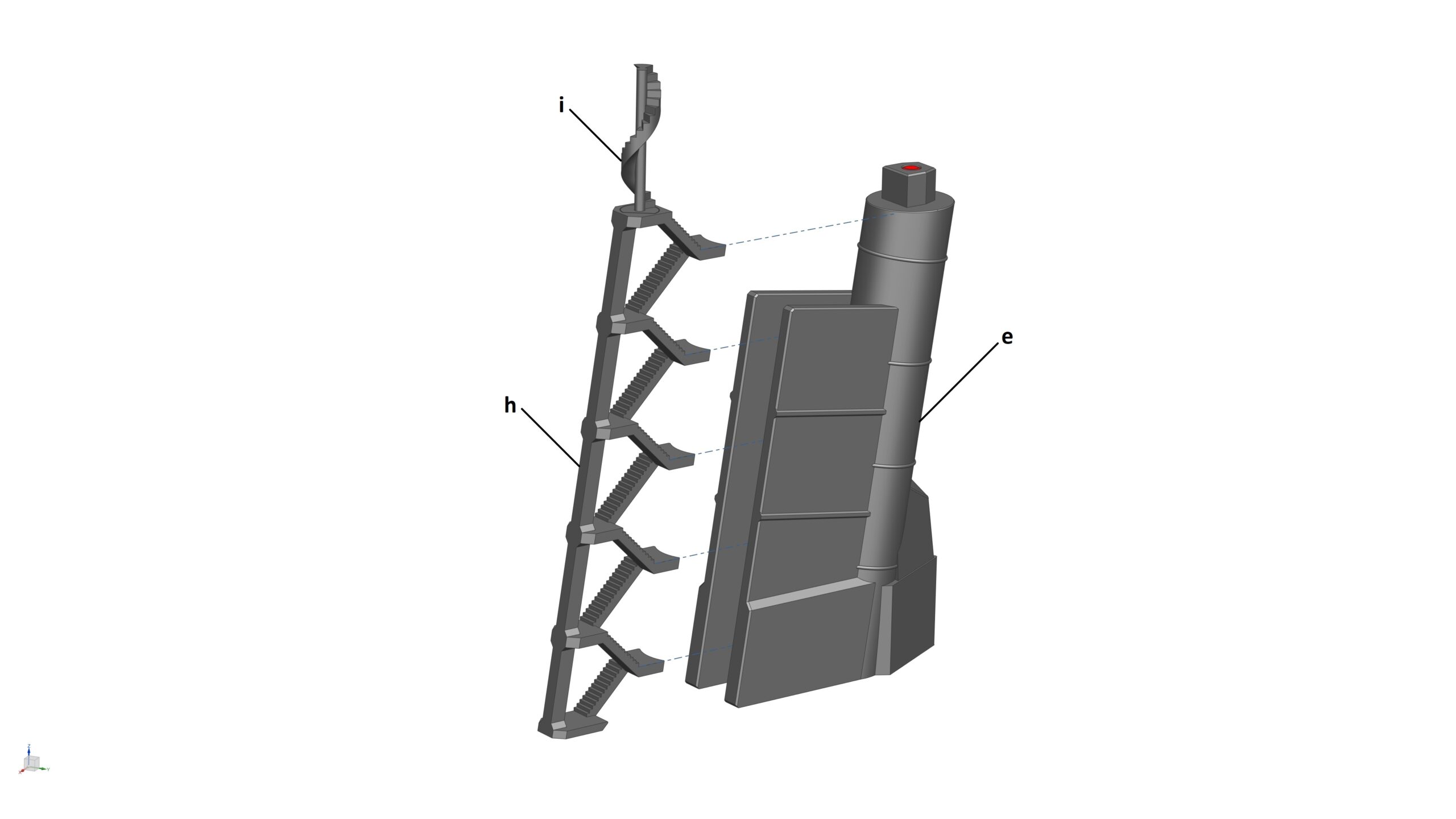
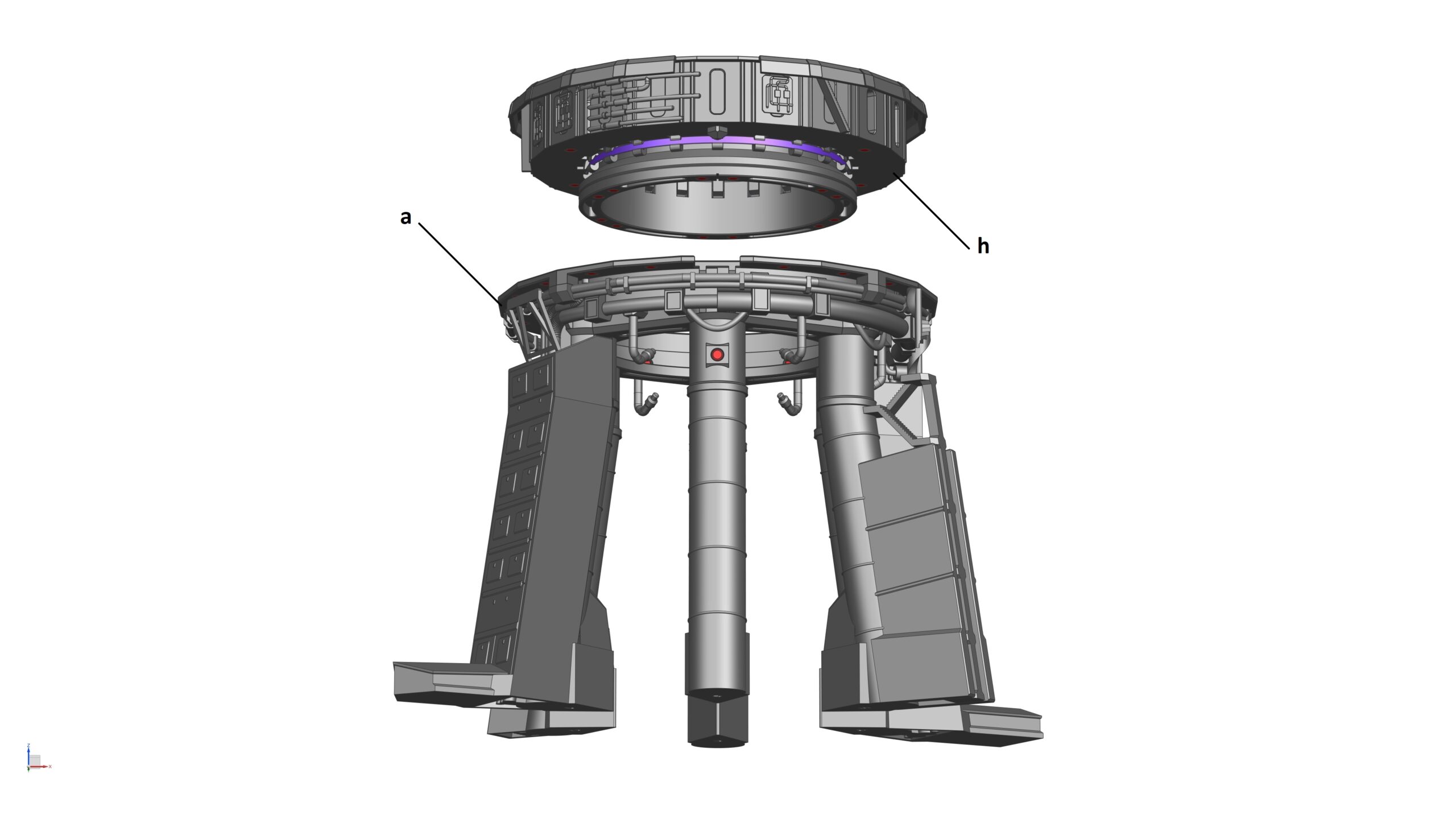
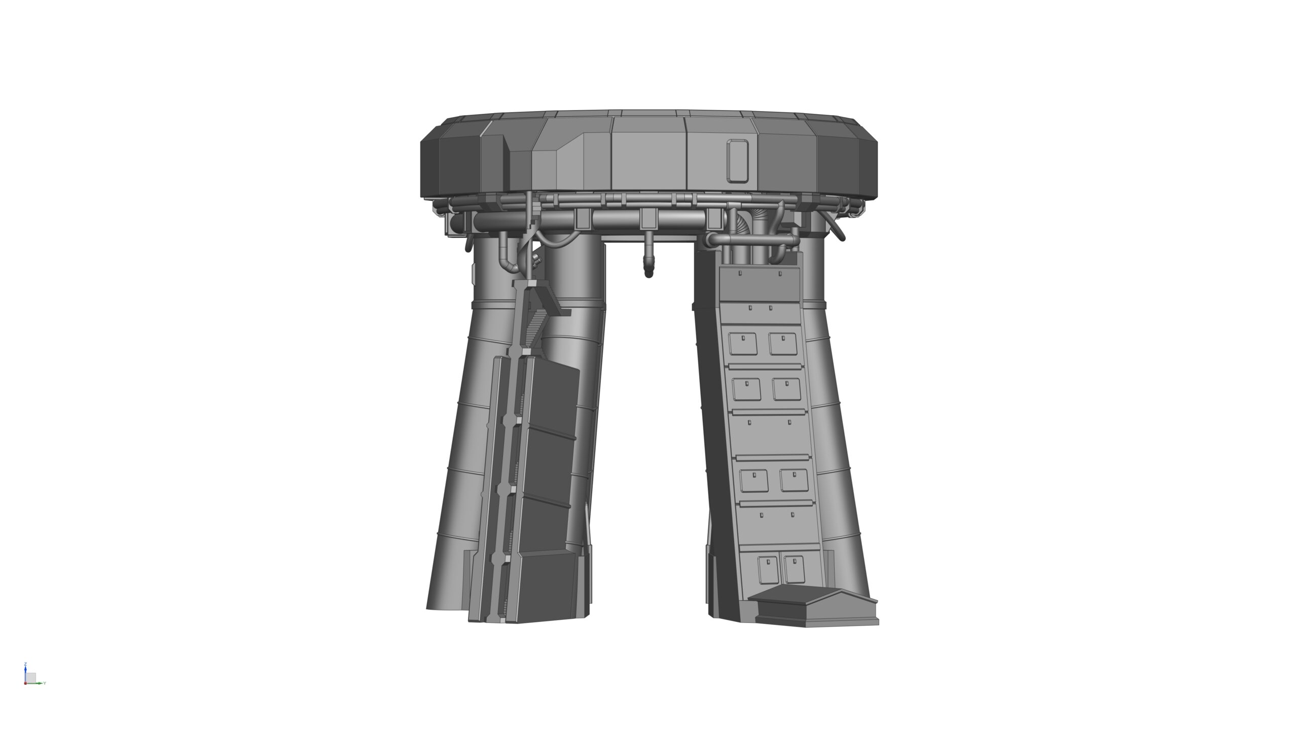
Please note: I already saved the STL for each part in the orientation I printed them on my FDM printer. Hence, when you load the STL in your slicer software, you don’t need to orientate them again, unless you want to try to print them in a different orientation.

Below are some tips.

  • At STEP 1, you’ll find 2 STL’s in the folder called OLM-S2 Assembly and OLM-S2 Assembly (without shields) . If you load these files, you’ll see the fully assembled OLM-S2 model. This will help you understand where each and every part is fitted on the model.

  • At STEP 2, all 6x Legs can be printed without support. Only the Leg_1_Support Frame and the Stair need support.
    If you want to add more weight to your OLM-S2 model to increase stability, use the Hollowed Version instead. These Legs have a cavity inside where you can pour sand into them.

  • At STEP 3, you MUST print the Sliding Ring before the Inner Ring. This is because these two parts are interlocked. Once you’ve printed the Inner Ring to at least about 15mm height (or just before it starts to print the “crown”), pause the print, drop the Sliding Ring into the Inner Ring, then resume printing. Once the Inner Ring is complete, the Sliding Ring is trapped in the middle and can only slide up/down to a certain distance (which was designed specifically for the Booster holding mechanism to work). Failure to follow this instruction meaning you won’t be able to install the Sliding Ring to the Inner Ring

  • At STEP 3, If you struggle to print the Finger (a.k.a. “hold down clamps”), use the Finger (Simplified) version instead. The only difference btw the two is the standard design has a slightly larger area on its top face (hence more contact area with the Booster). However, you’ll need to print this part vertically. The simplified version can be printed flat on the bed, hence easier but less contact area with the Booster

  • At STEP 8, although you can print the Dowel Pin, QD Case_Pin 1 and QD Case_Pin 2, I highly recommend you to purchase these parts instead. The Dowel Pin will allow the QD Plate to slide in/out of the QD hood smoother, and the QD Case Pins are only 2mm in dia. You can easily get some plastic, or metal rod in this dia on the Internet and just cut them into length rather than having to print them.

  • All magnet holes can be printed without support regardless of their positions/orientations on the model. Please don’t generate support for these holes (unless you really need to). Otherwise, you may struggle to remove support inside the holes due to restricted access. The easiest way to stop Cura from generating support inside these magnet holes is to use support blocker to cover the holes.

  • This OLM-S2 model is designed in such a way that allows you to assemble and disassemble the model into piece part level because almost every part is held together by magnets. However, if you prefer to glue everything (or some parts together), that’s also fine.

  • This model is designed at 1:96 scale and I highly recommend you to print at this scale to achieve the highest quality. However, if you decided to print it at a different scale, please be aware that the magnets I selected for this model will no longer fit and you will have to glue the parts together.

How to assemble the OLM-S2

So now you’ve got all your parts printed? Great! Let’s assemble the model!

I’ll take you through the assembly process step by step but before that, you need to purchase some items:

  • 5mm dia x 3mm thick N42 Neodymium magnets (LINK) | Qty: 120-off
  • Rubber band (LINK) | Qty: 1-off (This is the Rubber band I use, you don’t need to use the exact same one, any rubber band is fine)
  • BASF Forward AM Ultrafuse TPC 45D Silver 2.85mm 500g (LINK) | Qty: 1-off spool (I simply cut this filament into short strands to make the flexible pipes for the model, you don’t need to use the exact same one, any flexible filament is fine)
  • 5mm Diameter x 36 mm Length Steel Parallel Dowel Pin  (LINK) | Qty: 2-off (This part is optional but I highly recommend)
  • 2mm Diameter x 200mm Length Acrylic Round Rod (LINK) | Qty: 4-off (This part is optional but I highly recommend, you can also use steel or brass rods)
  • Super glue (LINK) | Qty: 1 bottle

STEP 1: ‘Dry’ assemble the model

At this step, all I want you to do is try to stack all the parts together to get a good understanding of where they are located. Because there are a lot of magnets you need to fit during the assembly process, doing this first step will give you an idea of how to fit the magnets in each part correctly. Please use the ‘OLM_S2 Assembly.stl’ and the photos below if required.

STEP 2: Assemble the Legs

Parts required (refer to the photos below)

  • 1x Leg_1_S2 (a)
  • 1x Leg_2_S2 (b)
  • 1x Leg_3_S2 (c)
  • 1x Leg_4_S2 (d)
  • 1x Leg_5_S2 (e)
  • 1x Leg_6_S2 (f)
  • 1x Leg_1_Support Frame_S2 (g)
  • 1x Stair (h)
  • 1x Spiral Stair (i)
  • 6x Magnets (5mm dia x 3mm thick) (highlighted in red)

Assembly process

  1. STEP 2a: Glue 1x magnet (5mm dia x 3mm thick) into its pocket at the top of each Leg
  2. STEP 2b: Glue Leg_1_Support Frame into its slot in Leg_1
  3. STEP 2c: Glue Spiral Stair to Stair
  4. STEP 2d: Glue Stair to Leg_5

STEP 3: Assemble the Booster holding mechanism

Parts required (refer to the photos below)

  • 20x Finger_S2 (a)
  • 1x Inner Ring_S2 (b)
  • 1x Sliding Ring_S2 (c)
  • 1x Rubber band (d) (highlighted in purple)
  • 2x Key_S2 (e)
  • 1x Orbital Launch Mount_Top (f)
  • 18x Magnets (5mm dia x 3mm thick) (highlighted in red)

Assembly process:

  1. STEP 3a: Glue 12x magnets (5mm dia x 3mm thick) into their pockets at bottom of the Inner Ring
  2. STEP 3b: Install 1x Finger to the Inner Ring (follow instructions in the photo below). Once installed correctly, the Finger should pivot freely around the cylindrical rod
  3. STEP 3c: Repeat the process until all 20x Fingers are installed to the Inner Ring
  4. STEP 3d: Stretch a rubber band (use more than one if needed) and insert it into the cut-out slot at the bottom of each Finger. As the rubber band is being stretched, its tension keeps all 20x Fingers at their up right positions, which also pushes the Sliding Ring down

    To quickly validate whether the Booster holding mechanism has been assembled correctly or not, use 2x Keys to push the Sliding Ring upward through any two opposite slots at the bottom of the Inner Ring. If all 20x Fingers fully extend/retract smoothly together, that means you have completed this step. If not, check the Fingers/Rubber band to ensure they have been installed correctly.

  5. STEP 3e: Glue 6x magnets (5mm dia x 3mm thick) into their pockets at the top and bottom faces of the Orbital Launch Mount_Top.

STEP 4: Assemble the Booster holding mechanism to the Orbital Launch Mount Top

Parts required (refer to the photos below)

  • 1x Booster holding mechanism from STEP 3 (a)
  • 1x Orbital Launch Mount_Top_S2 from STEP 3 (b)
  • 2x Key_S2 from STEP 3 (c)

Assembly process

  1. STEP 4a: Use 2x Keys to push the Sliding Ring upward through any two opposite slots at the bottom of the Inner Ring
  2. STEP 4b: Slide both Keys clockwise to lock the Sliding Ring in place and all Fingers in their fully extended positions
  3. STEP 4c: Install the Booster holding mechanism to the bottom of the Orbital Launch Mount_Top. Ensure that the alignment cut-out slot at the bottom of the Inner Ring is aligned with the cut-out of the Orbital Launch Mount_Top (where the Booster QD is located later)

    All Fingers must be in their fully extended positions before STEP 4c can be carried out. Otherwise, the Booster holding mechanism can’t be installed to the Orbital Launch Mount_Top due to clashes

  4. STEP 4d: Slide the Keys counter-clockwise and remove them. The Fingers should now fully retracted into their slots in the Orbital Launch Mount_Top

STEP 5: Assemble the Orbital Launch Mount Bottom

Parts required (refer to the photos below)

  • 1x Orbital Launch Mount_Bottom_S2 (a)
  • 1x Pipe System_S2 (b)
  • 6x Nozzle_S2 (c)
  • 2x Strand of flexible filament (2.85mm dia) (d)
  • 68x Magnets (5mm dia x 3mm thick) (highlighted in red)

Assembly process

  1. STEP 5a: Glue 52x magnets (5mm dia x 3mm thick) into their pockets at the top, bottom, and side faces of the Orbital Launch Mount_Bottom
  2. STEP 5b: Glue 4x magnets (5mm dia x 3mm thick) into their pockets at the top of the Pipe System
  3. STEP 5c: Glue 2x magnets (5mm dia x 3mm thick) into the pocket on each Nozzle
  4. STEP 5d: Cut 2x equal strand of flexible filament (2.85mm dia) into appropriate length and use them to connect the Nozzles together (3x Nozzles per strand)
  5. STEP 5e: Glue one end of each filament strand into the open-end pipes on the Pipe System*
  6. STEP 5f: Assemble the Pipe System, Nozzles, and the filament strands to the Orbital Launch Mount_Bottom

STEP 6: Assemble the Legs to the Orbital Launch Mount Top & Bottom

Parts required (refer to the photos below)

  • 1x Orbital Launch Mount_Bottom from STEP 5 (a)
  • 1x Leg_1 from STEP 2 (b)
  • 1x Leg_2 from STEP 2 (c)
  • 1x Leg_3 from STEP 2 (d)
  • 1x Leg_4 from STEP 2 (e)
  • 1x Leg_5 from STEP 2 (f)
  • 1x Leg_6 from STEP 2 (g)
  • 1x Orbital Launch Mount_Top from STEP 4 (h)

Assembly process

  1. STEP 6a: Install each Leg into its correct position under the Orbital Launch Mount_Bottom

    Each Leg is numbered from 1 to 6. Their correct positions are also marked on the inner face of the Orbital Launch Mount_Bottom for easy alignment

  2. STEP 6b: Install the Orbital Launch Mount_Top to the Orbital Launch Mount_Bottom

STEP 7: Assemble the Steel Covers

Parts required (refer to the photos below)

  • 8x Steel Cover_1_S2 (a)
  • 1x Steel Cover_2_S2 (b)
  • 1x Steel Cover_3_S2 (c)
  • 4x Steel Cover_4_S2 (d)
  • 3x Steel Cover_5_S2 (e)
  • 2x Steel Cover_6_S2 (f)
  • 19x Magnets (5mm dia x 3mm thick) (highlighted in red)
  • 1x Sub-assembly from STEP 6

Assembly process

  1. STEP 7a: Glue 1x magnets (5mm dia x 3mm thick) into its pocket on each Steel Cover
  2. STEP 7b: Install all 19x Steel Covers on the OLM

STEP 8: Assemble the Booster Quick Disconnect (QD)

Parts required (refer to the photos below)

  • 1x QD Case Lid_S2 (a)
  • 1x QD Case (Top)_S2 (b)
  • 1x QD Case (Mid)_S2 (c)
  • 1x QD Case (Bottom)_S2 (d)
  • 1x QD Plate_S2 (e)
  • 2x QD Case_Link 1_S2 (f)
  • 2x QD Case_Link 2_S2 (g)
  • 2x QD Case_Pin 1_S2 (h)
  • 2x QD Case_Pin 2_S2 (i)
  • 2x Dowel Pin_S2 (j)
  • 9x Magnets (5mm dia x 3mm thick) (highlighted in red)
  • 1x Sub-assembly from STEP 7

Assembly process

  1. STEP 8a: Glue 4x magnets (5mm dia x 3mm thick) into their pockets at the rear and bottom faces of the QD Case (Top)
  2. STEP 8b: Glue 2x magnets (5mm dia x 3mm thick) into their pockets at the front face of the QD Case (Mid)
  3. STEP 8c: Glue 1x magnet (5mm dia x 3mm thick) into its pocket at the front face of the QD Case (Bottom)
  4. STEP 8d: Glue the QD Case Top, Mid, and Bottom together

    For perfect alignment, temporarily install these 3 parts onto the Sub-assembly from STEP 7 and glue them together in their installed position

  5. STEP 8e: Cut 2x pieces of 2mm dia rod into length (approx. 37mm) to make 2x QD Case_Pin 2, then use them to install 2x QD Case_Link 1 to the QD Case (Top)
  6. STEP 8f: Cut 2x pieces of 2mm dia rod into length (approx. 33mm) to make 2x QD Case_Pin 1, then use them to install 2x QD Case_Link 2 to the QD Case (Top)
  7. STEP 8g: Glue 2x magnets (5mm dia x 3mm thick) into their pockets at the front face of the QD Plate and 2x Dowel Pin to the rear. Slide the assembled QD Plate into the QD Case (Top)
  8. STEP 8h: Fully open and close the QD Case Lid to ensure all the linkages work fine
  9. STEP 8i: Install the Booster QD to the OLM (Sub-assembly from STEP 7)

Congratulations, you have fully built the OLM-S2 model at this point!

STEP 9: Assemble the BOOSTER-S2 to the OLM-S2

Parts required (refer to the photos below)

  • 1x OLM-S2 from STEP 8
  • 2x Key_S2 from STEP 3
  • 1x BOOSTER-S2

Assembly process

  1. STEP 9a: Insert 2x Keys to any two opposite slots at the bottom of the Orbital Launch Mount_Bottom
  2. STEP 9b: Lower the BOOSTER-S2 into the OLM-S2. Whilst holding the BOOSTER-S2 at the with one hand, use the other hand to push one key upward and slide it clockwise to ‘partially’ extend the Fingers and lock them into position. Switch hand and repeat with the other key. Once both Keys are in, all 20x Fingers should be fully extended to support the weight of the BOOSTER-S2
  3. STEP 9c: Open the QD Case Lid (if haven’t done so already), and slide the QD Plate forward. The 2x magnets on the OLM’s QD Plate should mate with those on the BOOSTER-S2’s QD plate

Congratulations, you have successfully installed and secured the BOOSTER-S2 to the OLM-S2. To remove the BOOSTER-S2, repeat the above steps in reverse

Subscribe
Notify of
guest
0 Comments
Inline Feedbacks
View all comments
0
Please vote & feedback on this product :)x