How to Print & Assemble The OLIT-S1

How to print the OLIT-S1

If you want to save this How-To instruction as a pdf file (and print it out later if needed), simply copy the URL of this page and paste it to https://www.printfriendly.com/ . Printfriendly will generate a printer-friendly pdf of the page with all the texts and images for you.

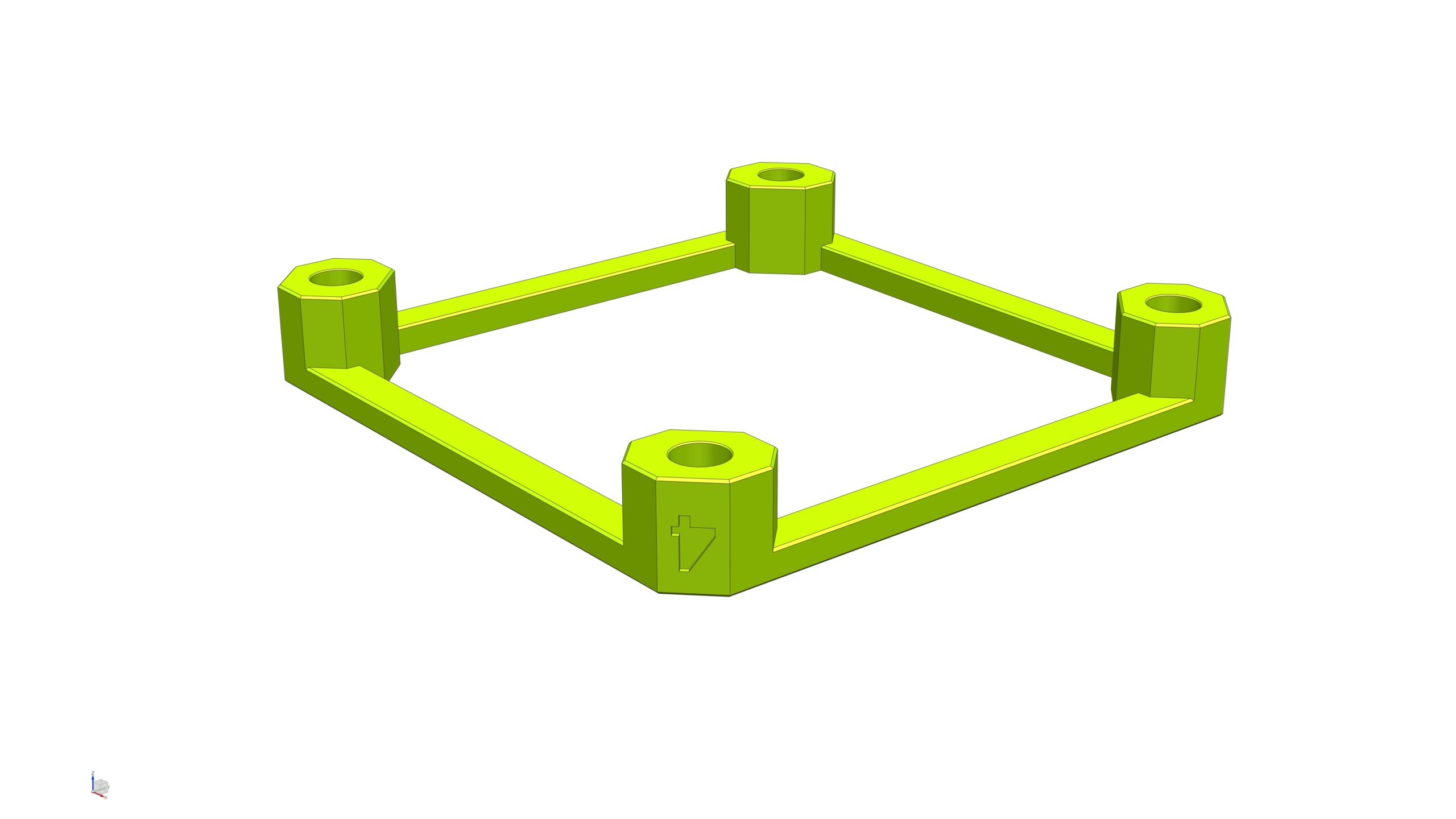
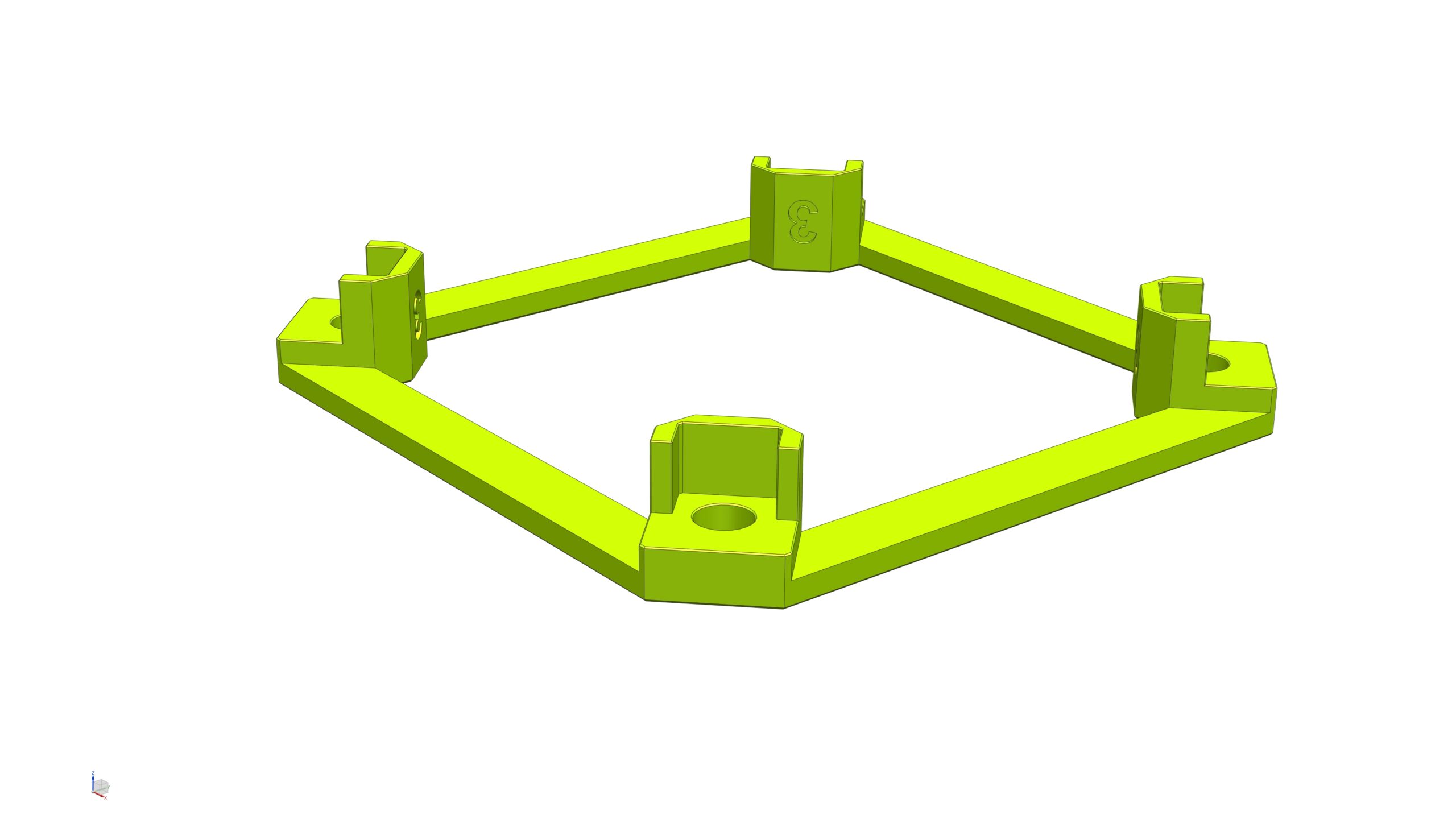
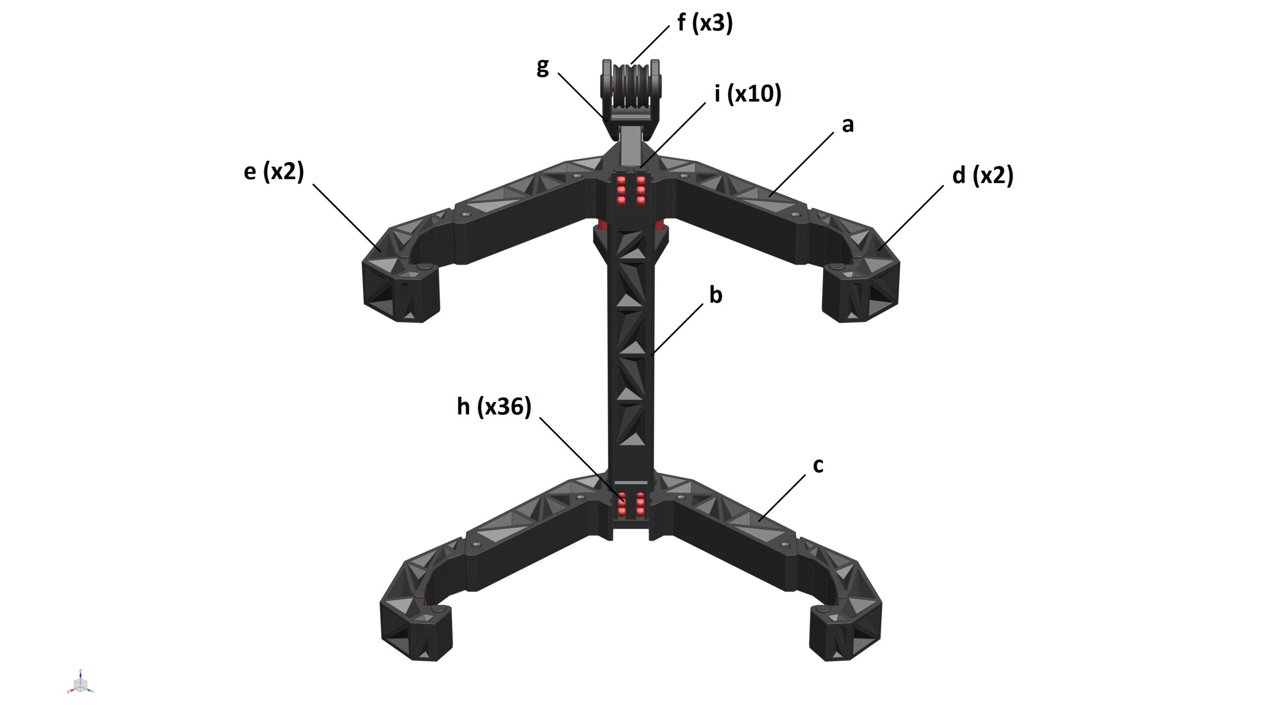
All of the STL files are really straight forward to print. All you need to do is load them into your slicer software (I use Cura), select your desirable settings (e.g. layer height, infill percentage, etc.) and slice the parts. I used 0.4mm nozzle 0.2mm layer height to print ALL parts of this model.

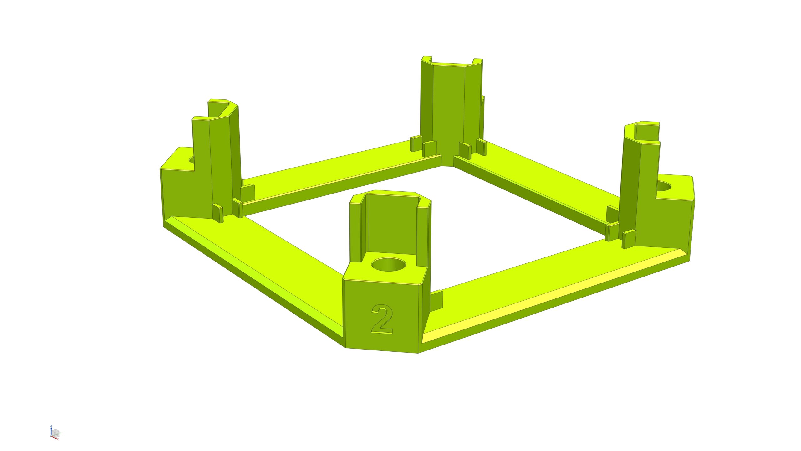
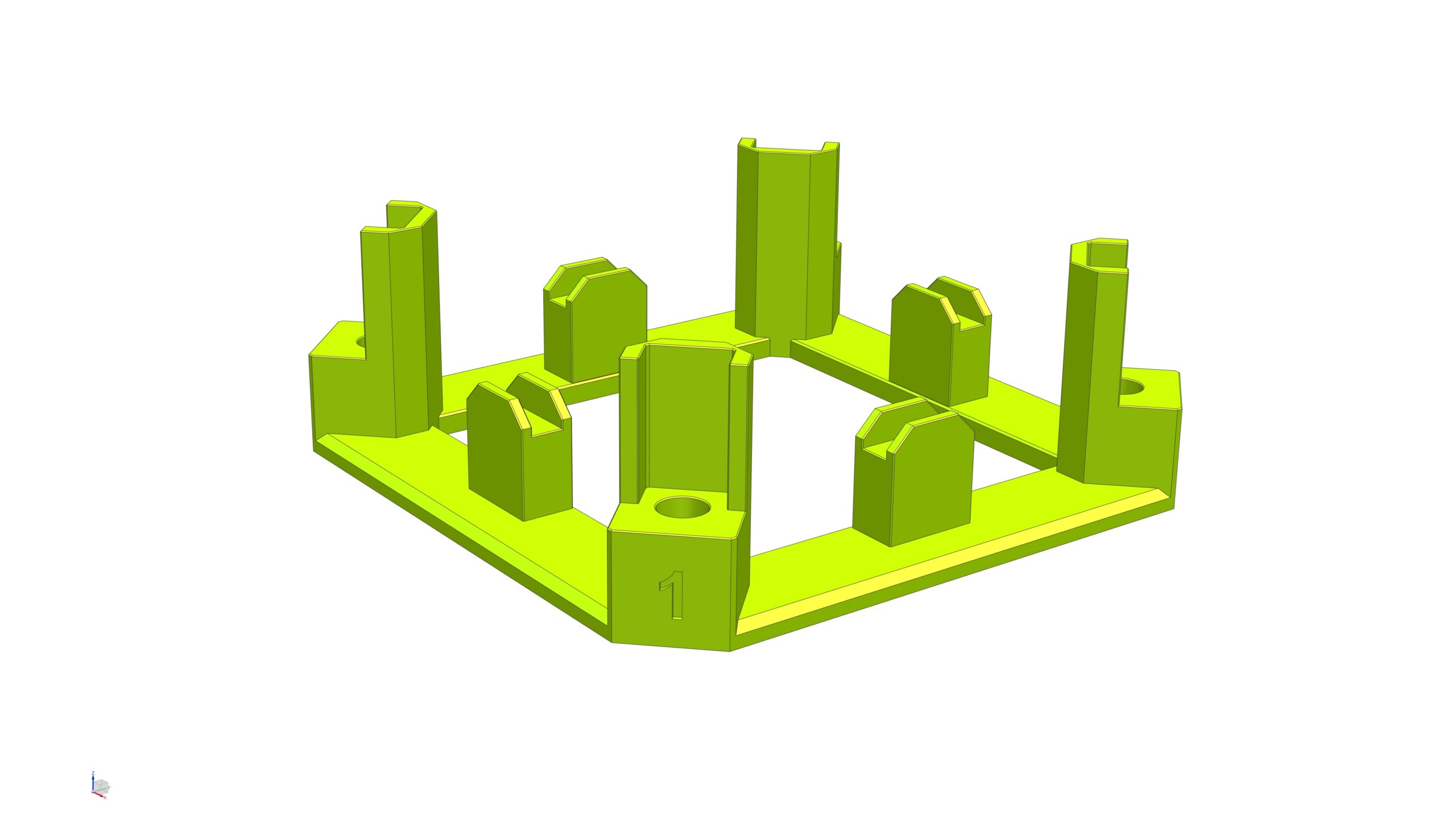
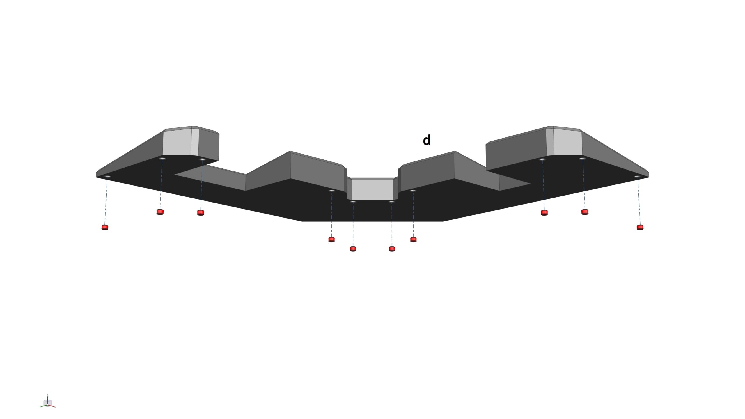
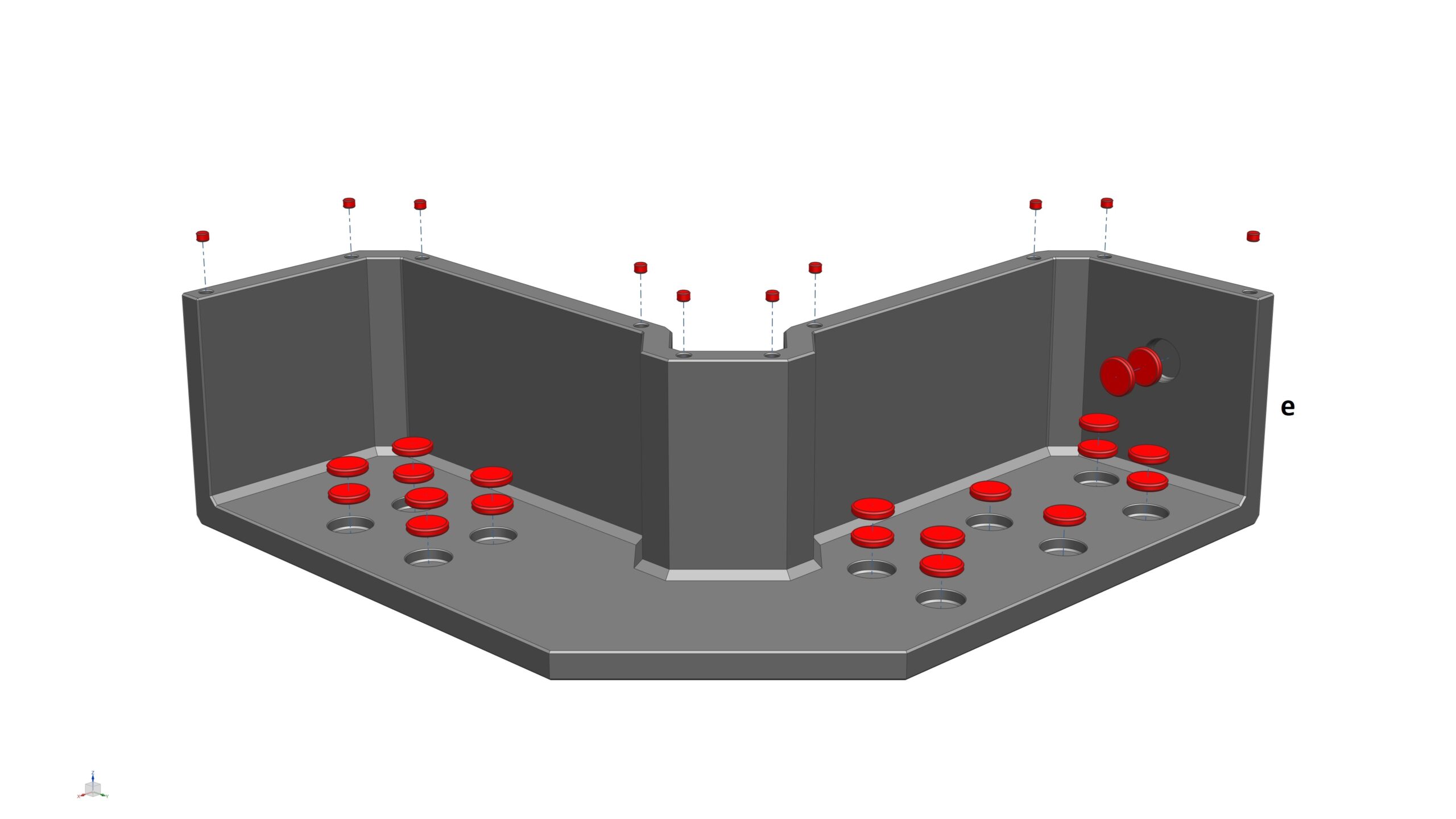
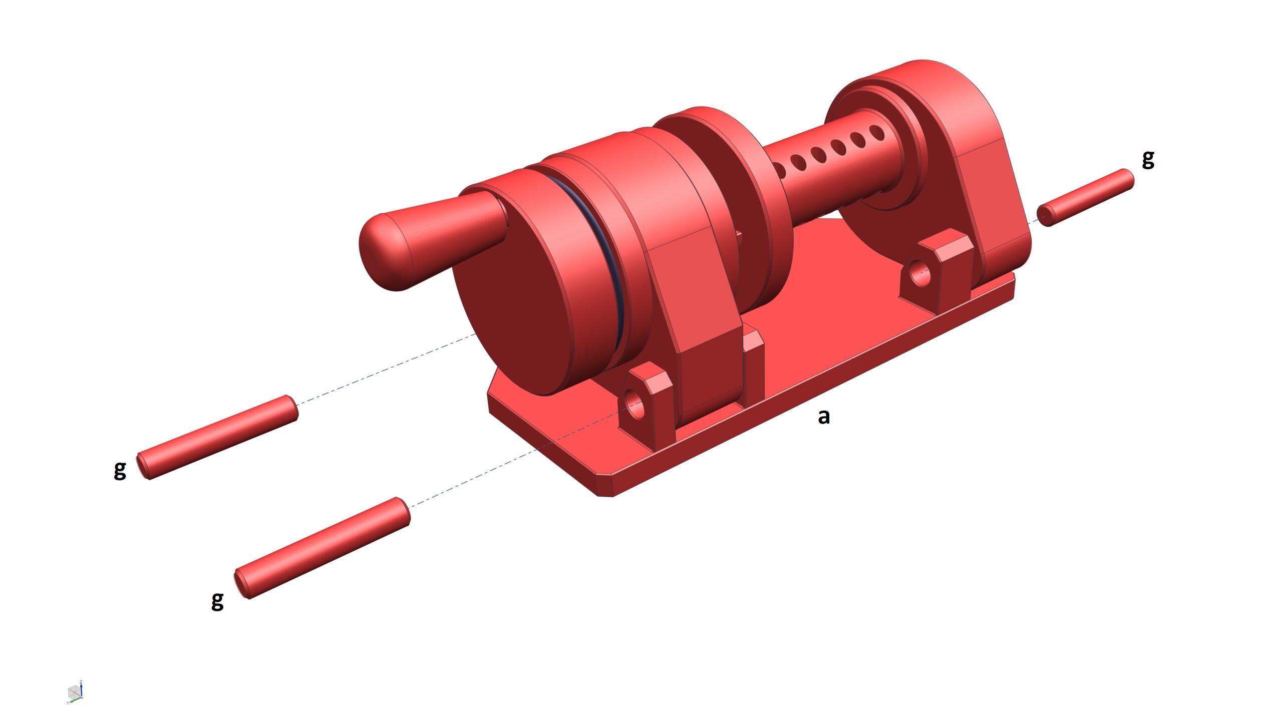
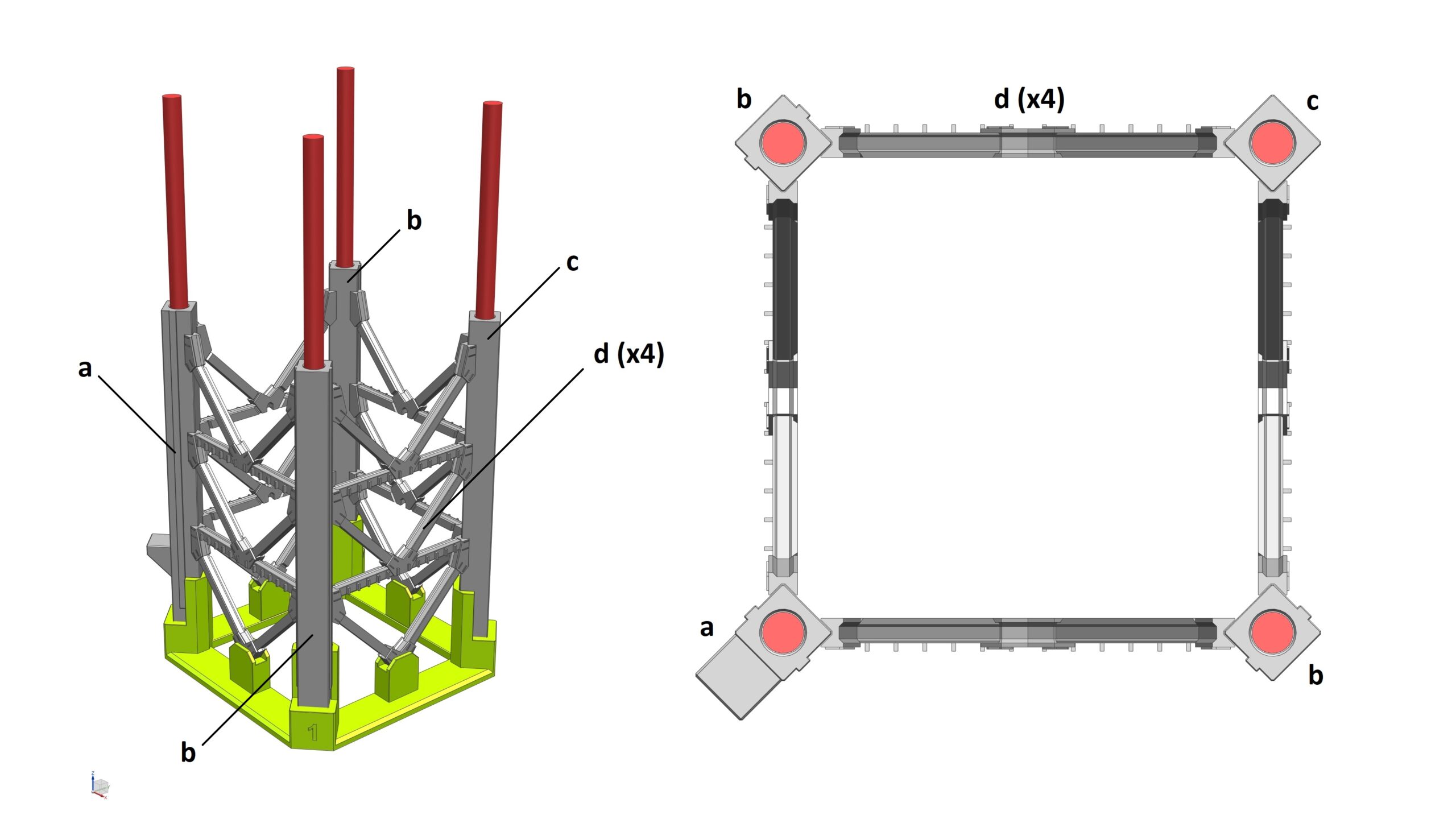
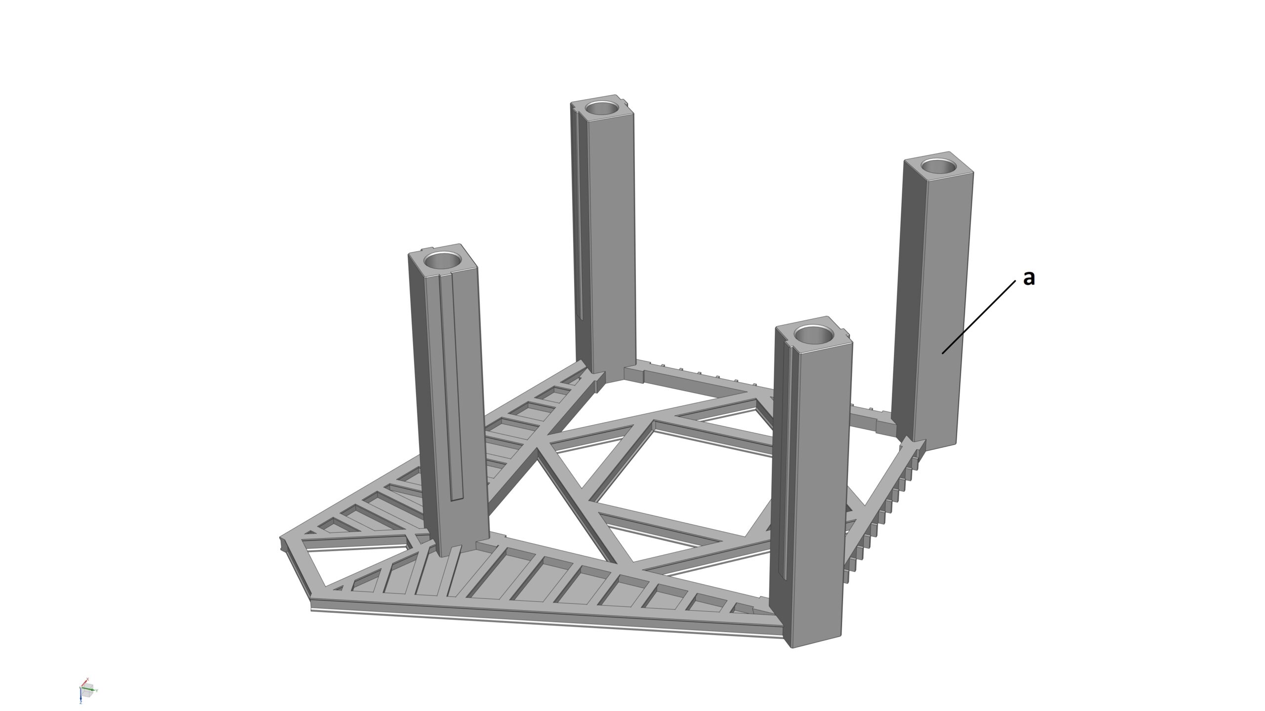
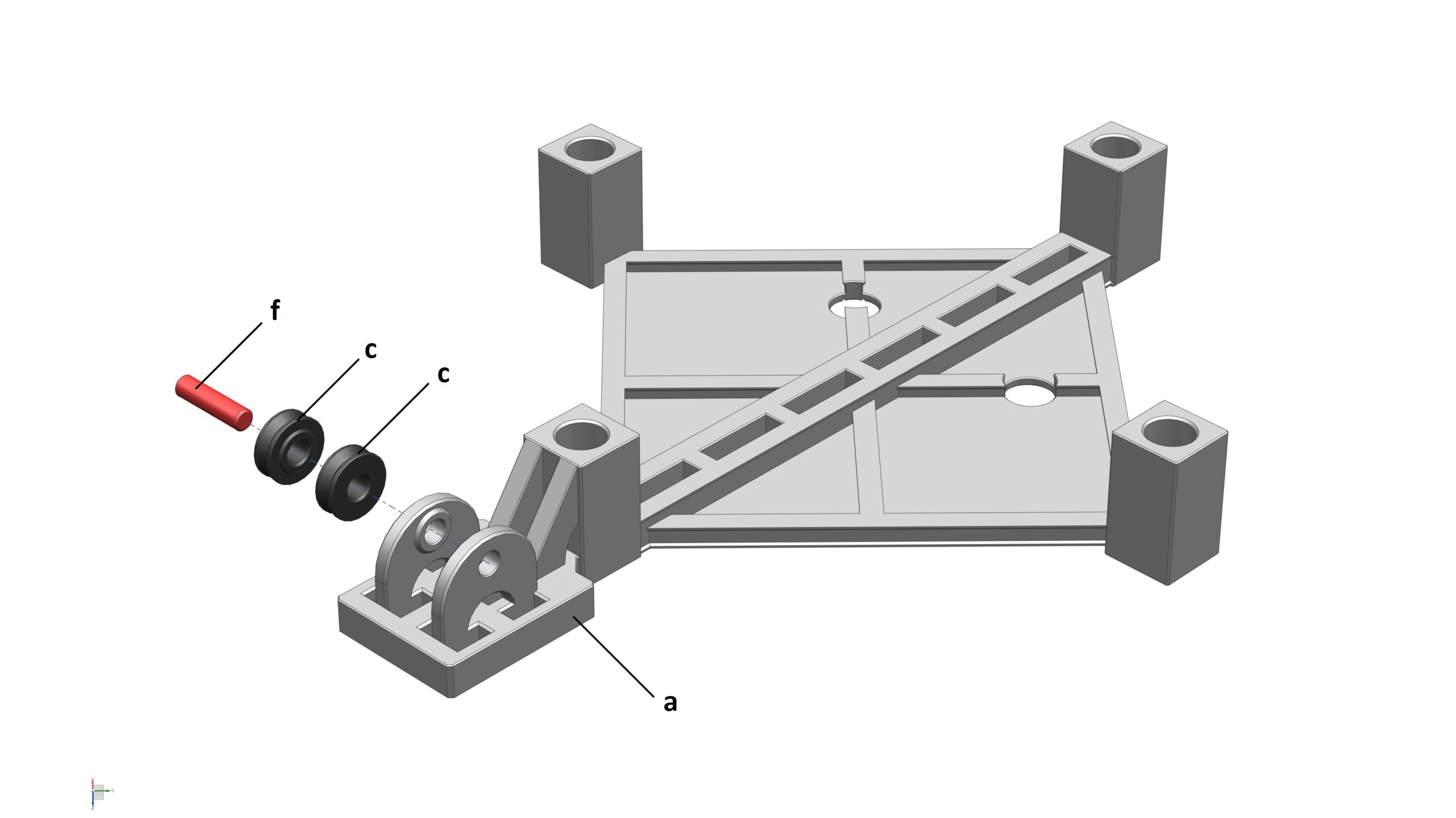
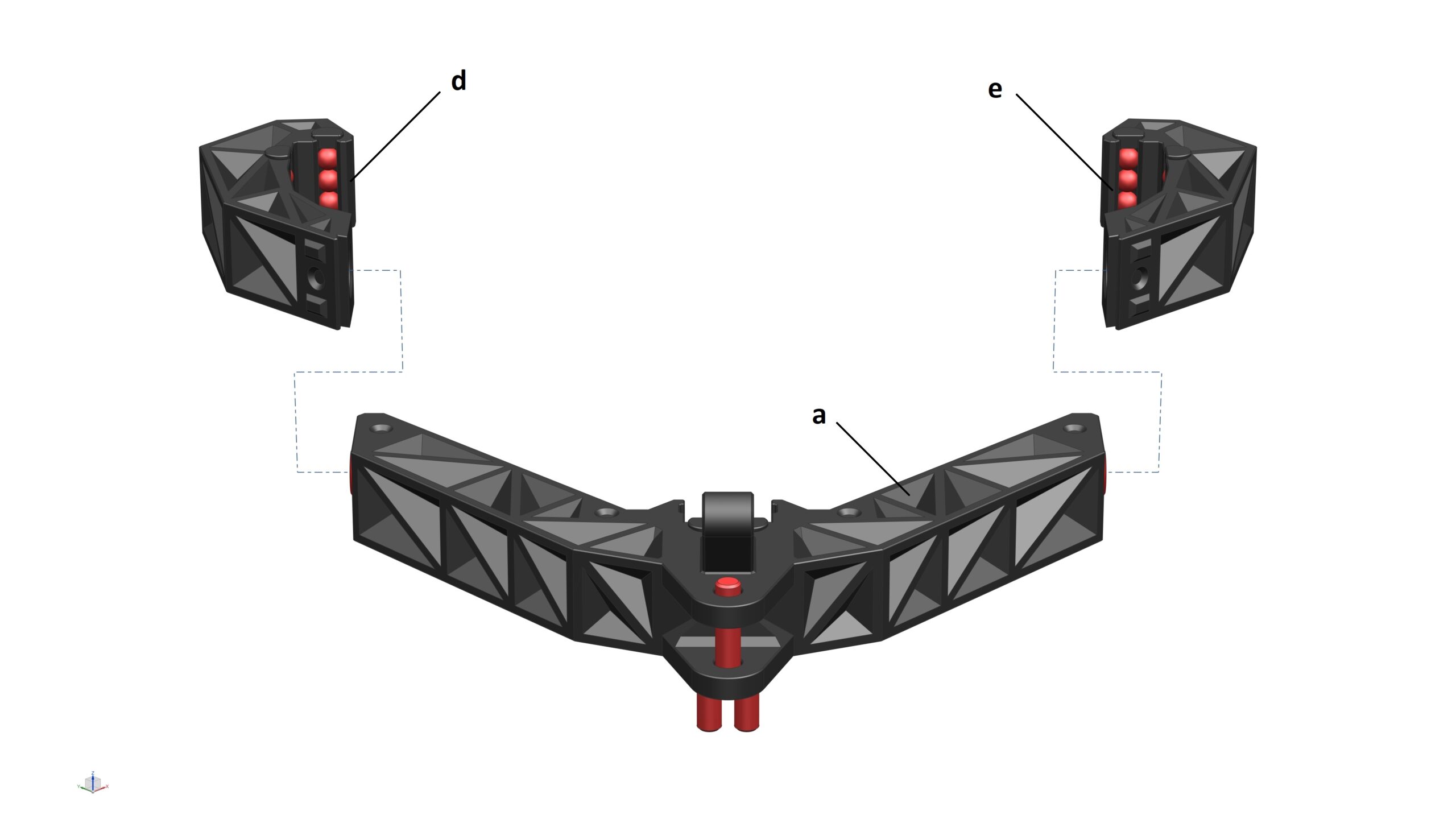
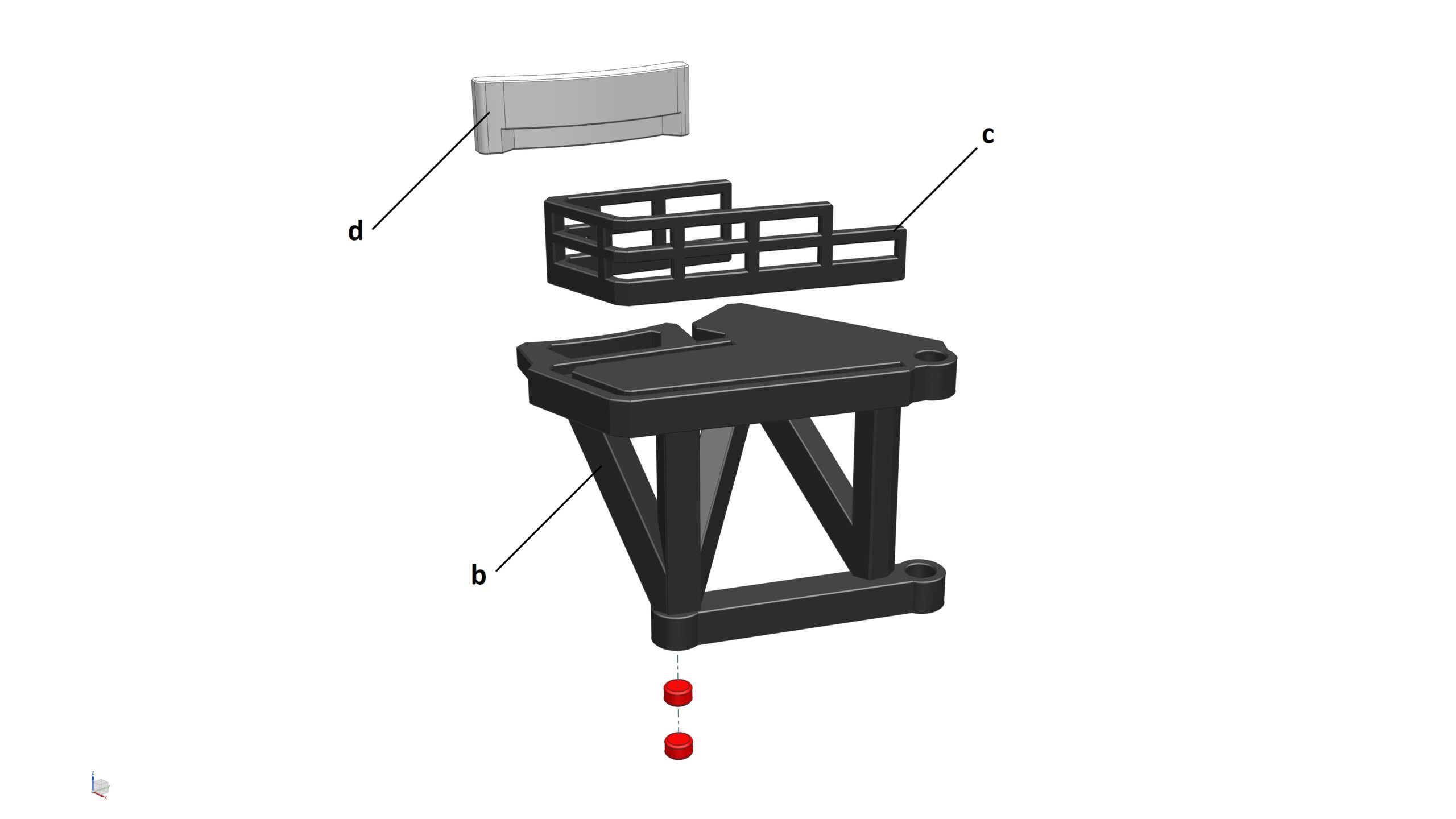
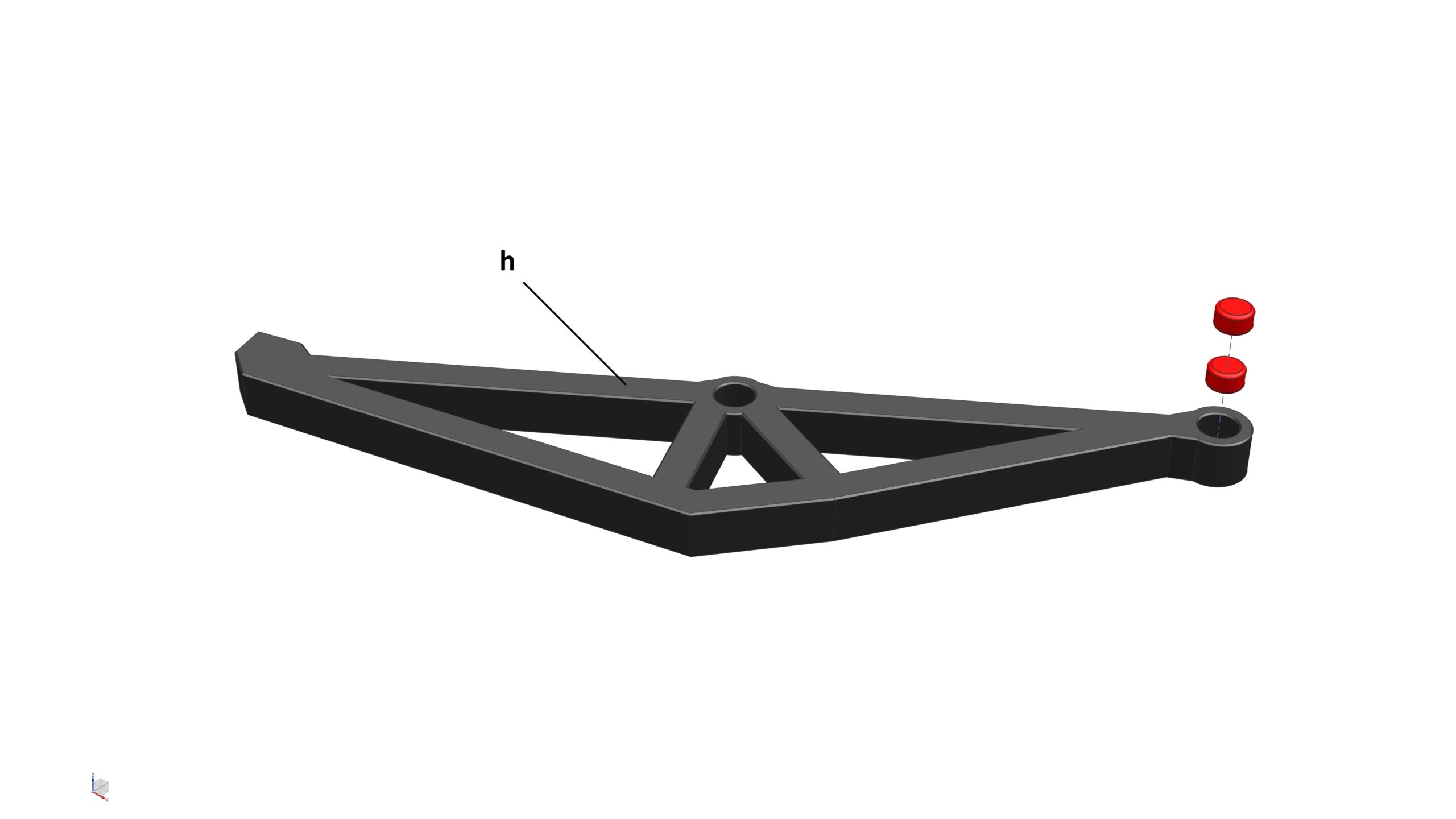
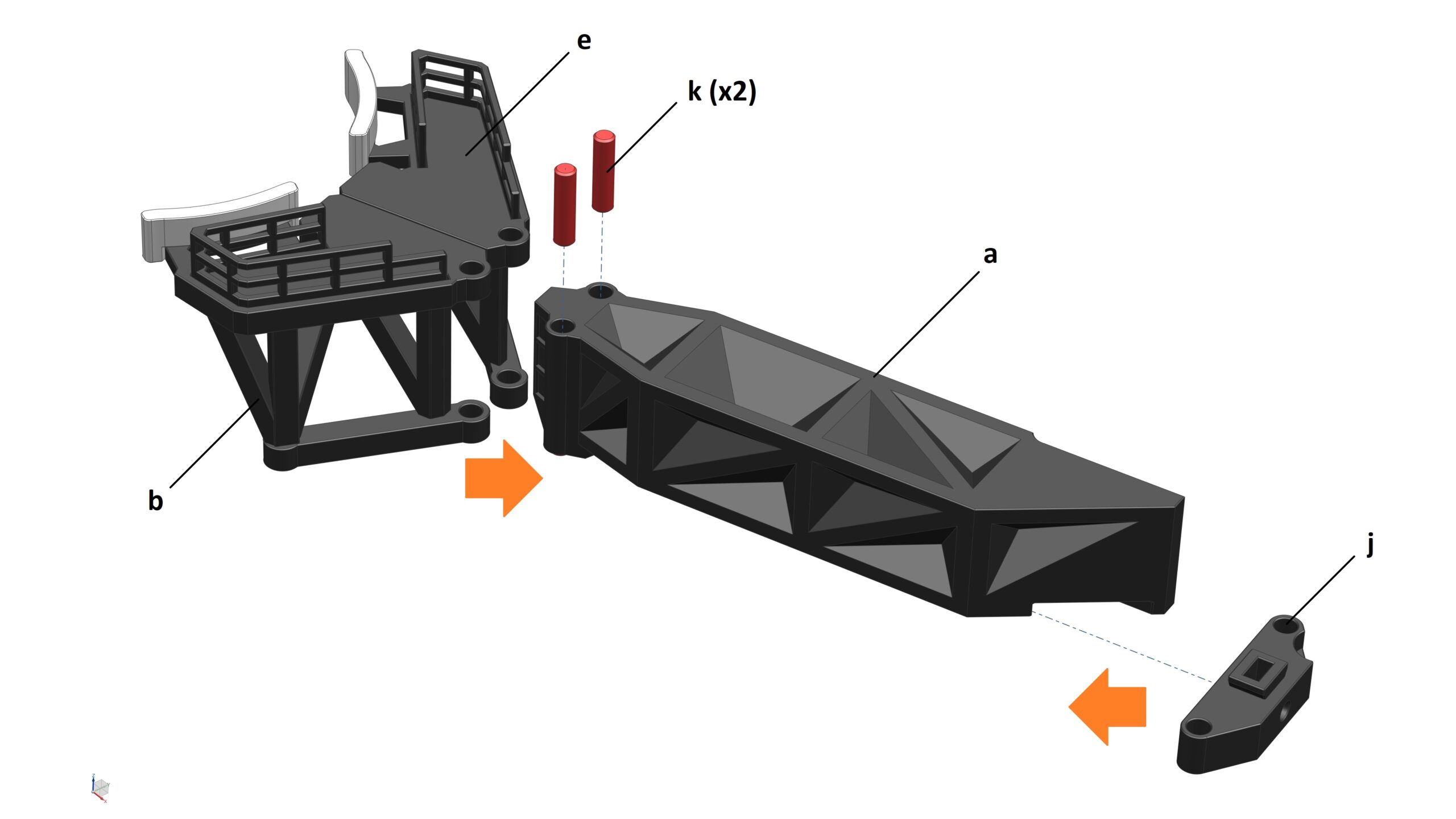
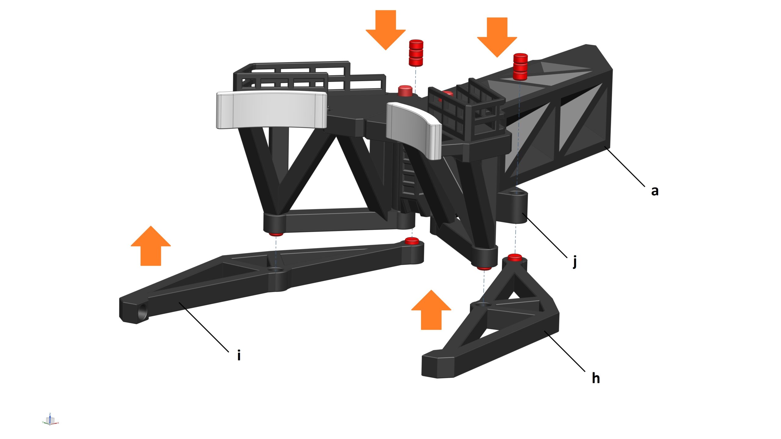
Please note: I already saved the STL for each part in the orientation I printed them on my FDM printer. Hence, when you load the STL in your slicer software, you don’t need to orientate them again, unless you want to try to print them in a different orientation.

Below are some tips

  • All magnet holes can be printed without support regardless of their positions/orientations on the model. Please don’t generate support for these holes (unless you really need to). Otherwise, you may struggle to remove support inside the holes due to restricted access. The easiest way to stop Cura from generating support inside these magnet holes is to use support blocker to cover the holes.

  • I highly recommend you to purchase and use the Steel Dowel Pins listed below (so that the parts can move smoothly around the joints). However, if you don’t really bother about the moving parts of the model, you can print the Dowel Pins instead – you can find STL’s of the Dowel Pins in various folders.

  • I highly recommend you to purchase and use the 10mm dia x 330mm L Steel Rods listed below so that you can use them in conjunction with the assembly fixtures to ensure that each section of the tower is built as accurately as possible. I purchased them at 330mm length because they are off-the-shelves items in the UK. You can purchase them in any other lengths as long as they are at least 230mm long.

  • I highly recommend you to purchase and use the 10mm dia x 1500mm L Steel Rods listed below to ensure that your OLIT tower is sturdy, especially if you plan to lift the Starship-S1 or Booster-S1 with it. These Steel Rods act like the skeleton of the model which they run all the way from the bottom of the Base to the top of the OLIT. You don’t need to get them exactly 1500mm long but ideally, you want their lengths to be between 1485mm – 1515mm. If you can’t get hold of these rods or don’t want to use them, you can still print some 10mm dia x 50mm Dowel Pins (see STEP 15) and use them to joint & glue the tower sections together.

  • At STEP 10, if you are planning to update your OLIT-S1 to the S2 version, please use the new version of the “Launch Tower_Section 9a” from the OLIT-S2 files. Do NOT use this file from the OLIT-S1

    _____

    At STEP 14, if you are planning to update your OLIT-S1 to the S2 version, please use the new version of the “QD Claw_Upper Arm_RH” and “QD Claw_Upper Arm_LH” from the OLIT-S2 files. Do NOT use this file from the OLIT-S1.

    Also, the “QD Claw_Lower Arm_RH“, “QD Claw_Lower Arm_LH“, “QD Claw_Upper Arm_Pad_RH“, and “QD Claw_Upper Arm_Pad_LH” are no longer required for the OLIT-S2

  • This model is designed at 1/96 scale and I highly recommend you to print at this scale to achieve the highest quality. However, if you decided to print it at a different scale, please be aware that the magnets I selected for this model will no longer fit and you will have to glue the parts together.

How to assemble this model?

So now you’ve got all your parts printed? Great! Let’s assemble the model. I’ll take you through the assembly process step by step but before that, you need to purchase some items:

  • 10mm dia x 2mm thick N42 Neodymium magnets (LINK) | Qty: 58-off
  • 5mm dia x 3mm thick N42 Neodymium magnets (LINK) | Qty: 62-off
  • 3mm dia x 2mm thick N42 Neodymium (LINK) | Qty: 26-off
  • 5mm dia x 20mm L Dowel Pin (LINK) | Qty: 14-off
  • 5mm dia x 28mm L Dowel Pin (LINK) | Qty: 12-off
  • 10mm dia x 330mm L Steel Rod (LINK) | Qty: 4-off
  • 10mm dia x 1500mm L Steel Rod (LINK) | Qty: 4-off
  • Ball Bearing 35mm O.D x 17mm I.D x 10mm Race Width (LINK) | Qty: 2-off
  • 5mm dia Steel Bearing Ball (LINK) | Qty: 36-off
  • Polyester Cord String 1mm dia (LINK) | Qty: 20 meters
  • M3 x 10mm Hex Socket Cap Screw (LINK) | Qty: 4-off
  • M3 Hex Nut (LINK) | Qty: 4-off
  • Super glue (LINK) | Qty: 1 bottle

STEP 0: Examine the model

At this step, all I want you to do is view the fully completed OLIT model as well the main sub-assemblies to get a good understanding of each section of the model and where all the parts are located. Because there are a lot of magnets you need to fit during the assembly process, doing this first step will give you an idea of how to fit the magnets in each part correctly. Please load the STL files in “STEP_00” folder using your CAD software or Slicer.

STEP 1: Prepare Assembly Fixtures

In order to build each section of the OLIT precisely, you’ll need to use a combination of assembly fixtures. These fixtures can be found in folder “STEP_01” (refer to the photos below):

  • 1x Assembly Fixture_1
  • 1x Assembly Fixture_2
  • 1x Assembly Fixture_3
  • 1x Assembly Fixture_4

STEP 2: Assemble the Base

Parts required (refer to the photos below):

  • 1x Base (a)
  • 1x Base Lid (b)
  • 2x Pulley_01 (c)
  • 1x Base Control Station Roof (d)
  • 1x Base Control Station (e)
  • 1x Base Control Station Support Beam (f)
  • 2x Dowel Pins (5mm dia x 20mm L) (g)
  • 20x Magnets (3mm dia x 2mm thick) (highlighted in RED)
  • 8x Magnets (5mm dia x 3mm thick) (highlighted in RED)
  • 20x Magnets (10mm dia x 2mm thick) (highlighted in RED)

Assembly process:

  1. STEP 2a: Glue 4x magnets (5mm dia x 3mm thick) into their pockets on the Base
  2. STEP 2b: Glue 4x magnets (5mm dia x 3mm thick) into their pockets on the bottom of the Base Lid. Insert 2x Pulley_01 to the Base Lid and secure them with the Dowel Pins
  3. STEP 2c: Glue 10x magnets (3mm dia x 2mm thick) into their pockets on the bottom of the Base Control Station Roof
  4. STEP 2d: Glue 10x magnets (3mm dia x 2mm thick) into their pockets on the top of the Base Control Station. Glue 20x magnets (10mm dia x 2mm thick) into their pockets on the bottom and side of the Base Control Station
  5. STEP 2e: Fit the Base Lid to the Base (the magnets should keep them together). At this STEP, I highly recommend you to fill the cavity in the Base with something heavy (e.g. sand, steel bars, etc.) to make the Base as heavy as possible. This will help increase the stability of the OLIT once you’ve completed the model
  6. STEP 2f: Glue the Base Control Station and Base Control Station Support Beam to the Base (note that the text on the Base must be visible as shown in the Front View pic below). DO NOT glue the Base Control Station Roof to anything!!!
  7. Finally, place the Base Control Station Roof onto the Base Control Station (the magnets should keep them together)

STEP 3: Assemble the Supply Reel to the Base

Parts required (refer to the photos below):

  • 1x Supply Reel_Base (a)
  • 2x Supply Reel_Spool End (b)
  • 1x Supply Reel_Spool (c)
  • 2x Dowel Pins (5mm dia x 28mm L) (d)
  • 4x Magnets (10mm dia x 2mm thick) (highlighted in RED)

Assembly process:

  1. STEP 3a: Glue 4x magnets (10mm dia x 2mm thick) into their pockets on the bottom of the Supply Reel_Base
  2. STEP 3b: Glue the 2x Supply Reel_Spool End to the ends of the Supply Reel_Spool. Ensure that the off-centre holes on the 2x Supply Reel_Spool End are aligned!
  3. STEP 3c: Install the Supply Reel_Spool sub-assembly to the Supply Reel_Base and secure with 2x Dowel Pins
  4. STEP 3d: Install the Supply Reel Sub-Assembly to the Base from STEP 2

STEP 4: Assemble the Drawworks to the Base

Parts required (refer to the photos below):

  • 1x Drawworks_Base (a)
  • 1x Drawworks_Motor Left End (b)
  • 1x Drawworks_Motor Right End (c)
  • 1x Crank Disc (d)
  • 1x Drawworks_Spool (e)
  • 1x Handle (f)
  • 5x Dowel Pins (5mm dia x 28mm L) (g)
  • 2x Ball Bearings
  • 3x Magnets (5mm dia x 3mm thick) (highlighted in RED)
  • 16x Magnets (10mm dia x 2mm thick) (highlighted in RED)

Assembly process:

  1. STEP 4a: Glue 6x Magnets (10mm dia x 2mm thick) into 3 pockets on the top face of the Drawworks_Base (3 stacks of 2 magnets each)
  2. STEP 4b: Glue 6x Magnets (10mm dia x 2mm thick) into 6 pockets on the bottom face of the Drawworks_Base
  3. STEP 4c: Glue 2x Magnets (10mm dia x 2mm thick) into the pockets on the bottom face of the Drawworks_Motor Left End . Insert & glue 2x Ball Bearings into the body Drawworks_Motor Left End
  4. STEP 4d: Glue 2x Magnets (10mm dia x 2mm thick) into the pockets on the bottom face and the side of the Drawworks_Motor Right End
  5. STEP 4e: Glue 1x Magnets (5mm dia x 3mm thick) into the pocket of the Crank Disc
  6. STEP 4f: Glue 1x Magnets (5mm dia x 3mm thick) into the pocket of the Drawworks_Spool
  7. STEP 4g: Glue 1x Magnets (5mm dia x 3mm thick) into the pocket of the Handle
  8. STEP 4h & 4i: Assemble all parts of the Drawworks together using Dowel Pins
  9. STEP 4j: Install the Drawworks Assembly to the Base from STEP 2

Lock/Unlock mechanism:

  • To wind the handle, push the Drawworks_Spool all the way to the RIGHT (Unlock position)
  • To lock the handle (to prevent the spool from unwinding itself by accident), push the Drawworks_Spool all the way to the LEFT (Lock position)

STEP 5: Assemble the Launch Tower Section 1

Parts required (refer to the photos below):

  • 1x Launch Tower_Section 1_Column 1 (a)
  • 2x Launch Tower_Section 1_Column 2 (b)
  • 1x Launch Tower_Section 1_Column 3 (c)
  • 4x Launch Tower_Section 1_Vertical Support Frame (d)
  • 2x Horizontal Support Frame (e)
  • 1x Assembly Fixture 1 (f)
  • 1x Assembly Fixture 3 (g)
  • 1x Assembly Fixture 4 (h)
  • 4x Steel Rods (10mm Dia x 330mm L) (i)

Assembly process:

  1. STEP 5a: Insert 4x Steel Rods into Assembly Fixture 1
  2. STEP 5b: Slide Launch Tower_Section 1_Columns into Assembly Fixture 1
  3. STEP 5c: Slide 4x Launch Tower_Section 1_Vertical Support Frame in between the Columns
  4. STEP 5d: Slide Assembly Fixture 3 all the way down over the Columns
  5. STEP 5e: Slide Assembly Fixture 4 over the Steel Rods to secure them into place. Apply a small amount of glue at all the joints between the Columns and the Vertical Support Frames and let it cure before proceeding to the next STEP
  6. STEP 5f: Rotate Fixture up-side-down and slide the sub-assembly in the middle all the way down
  7. STEP 5g: Manoeuvre 2x Horizontal Support Frames into place and glue them to the Vertical Support Frames
  8. STEP 5h: Once the glue is cured, remove all the Assembly Fixtures and Steel Rods

STEP 6: Assemble the Launch Tower_Section 2 (3, 6, & 7)

Parts required (refer to the photos below):

  • 3x Launch Tower_Section 2_Column 1 (a)
  • 1x Launch Tower_Section 2_Column 2 (b)
  • 4x Launch Tower_Section 2_Vertical Support Frame (c)
  • 3x Horizontal Support Frame (d)
  • 1x Assembly Fixture 2 (e)
  • 1x Assembly Fixture 3 (f)
  • 1x Assembly Fixture 4 (g)
  • 4x Steel Rods (10mm Dia x 330mm L) (h)

Assembly process:

  1. Follow the same guidance as per STEP 5 above to build the Launch Tower Section 2

As the Launch Tower_Section 2, 3, 6, & 7 are exactly identical, repeat STEP 6 to produce 4x Sections of the Tower. Section 4 & 5 (where the QD Arm is attached) are slightly different – see STEP 7 & 8 below)

STEP 7: Assemble the Launch Tower_Section 4

Parts required (refer to the photos below):

  • 3x Launch Tower_Section 2_Column 1 (a)
  • 1x Launch Tower_Section 4_Column 2 (b)
  • 4x Launch Tower_Section 2_Vertical Support Frame (c)
  • 3x Horizontal Support Frame (d)
  • 1x Assembly Fixture 2 (e)
  • 1x Assembly Fixture 3 (f)
  • 1x Assembly Fixture 4 (g)
  • 4x Steel Rods (10mm Dia x 330mm L) (h)

Assembly process:

  1. Follow the same guidance as per STEP 6 above to build the Launch Tower_Section 4

The ONLY difference between Section 4 and Section 2 is the Column 2.

STEP 8: Assemble the Launch Tower_Section 5

Parts required (refer to the photos below):

  • 3x Launch Tower_Section 2_Column 1 (a)
  • 1x Launch Tower_Section 5_Column 2 (b)
  • 4x Launch Tower_Section 2_Vertical Support Frame (c)
  • 3x Horizontal Support Frame (d)
  • 1x Assembly Fixture 2 (e)
  • 1x Assembly Fixture 3 (f)
  • 1x Assembly Fixture 4 (g)
  • 4x Steel Rods (10mm Dia x 330mm L) (h)

Assembly process:

  1. Follow the same guidance as per STEP 6 above to build the Launch Tower_Section 5

The ONLY difference between Section 5 and Section 2 is the Column 2.

STEP 9: Assemble the Launch Tower_Section 8

Parts required (refer to the photos below):

  • 1x Launch Tower_Section 8 (a)
  • 4x Launch Tower_Section 8_Vertical Support Frame (b)
  • 2x Horizontal Support Frame (c)

Assembly process:

  1. STEP 9a: Place Launch Tower_Section 8 up-side-down
  2. STEP 9b: Slide 4x Launch Tower_Section 8_Vertical Support Frame in between the columns. Apply a small amount of glue at all the joints between the Columns and the Vertical Support Frames and let it cure before proceeding to the next STEP
  3. STEP 9c: Manoeuvre 2x Horizontal Support Frames into place and glue them to the Vertical Support Frames

STEP 10: Assemble the Launch Tower_Section 9a & 9b

Parts required (refer to the photos below):

  • 1x Launch Tower_Section 9a (a) *
  • 1x Launch Tower_Section 9b (b)
  • 2x Pulley_02 (c)
  • 4x Pulley_03 (d)
  • 4x Launch Tower_Section 9_Vertical Support Frame (e)
  • 5x Dowel Pins (5mm dia x 20mm L) (f)

Assembly process:

  1. Insert 2x Pulley_02 to Launch Tower_Section 9a and secure them with Dowel Pin
  2. Insert 4x Pulley_03 to Launch Tower_Section 9b and secure them with Dowel Pins
  3. Glue Section_9a, Section_9b and 4x Launch Tower_Section 9_Vertical Support Frame together. Ensure that all the holes in the Columns of both sections are perfectly aligned. Tips: You can use the Assembly Fixtures and Steel Rods from previous STEP’s to help align these parts together before gluing

* Please note: If you are planning to update your OLIT-S1 to the S2 version, please use the new version of the “Launch Tower_Section 9a” from the OLIT-S2 files. Do NOT use this file from the OLIT-S1

STEP 11: Assemble the  Carriage

Parts required (refer to the photos below):

  • 1x Carriage_Upper Frame_Centre (a)
  • 1x Carriage_Middle Frame (b)
  • 1x Carriage_Lower Frame_Centre (c)
  • 2x Carriage_Side Frame_LH (d)
  • 2x Carriage_Side Frame_RH (e)
  • 3x Pulley_04 (f)
  • 1x Pulley_04_Travelling Block (g)
  • 36x Steel Ball (5mm Dia) (h)
  • 10x Ball Retainer (i)
  • 3x Dowel Pin (5mm Dia x 20mm L) (j)
  • 5x Dowel Pin (5mm Dia x 28mm L) (k)
  • 12x Magnet (10mm dia x 2mm thick) (highlighted in RED)


Assembly process:

  1. STEP 11a: Glue 4x magnets (in 2 stack of 2 each) into the pockets on both sides of the Carriage_Upper Frame_Centre. Insert 6x Steel Balls (in 2 stack of 3 each) into the holes and secure them in place with the Ball Retainers. Please note: The Steel Balls should be able to spin freely and the flat face of the Ball Retainer should be flush with the flat face of the Carriage_Upper Frame_Centre. Finally, insert the Dowel Pins (do not glue them)
  2. STEP 11b: Glue 4x magnets (in 2 stack of 2 each) into the pockets on both sides of the Carriage_Lower Frame_Centre. Insert the Dowel Pin
  3. STEP 11c: Glue 1x magnet into the pocket on the side of the Carriage_Side Frame_LH. Insert 6x Steel Balls (in 2 stack of 3 each) into the holes and secure them in place with the Ball Retainers. Please note: The Steel Balls should be able to spin freely and the flat face of the Ball Retainer should be flush with the flat face of the Carriage_Side Frame_LH.
  4. STEP 11d: Glue 1x magnet into the pocket on the side of the Carriage_Side Frame_RH. Insert 6x Steel Balls (in 2 stack of 3 each) into the holes and secure them in place with the Ball Retainers. Please note: The Steel Balls should be able to spin freely and the flat face of the Ball Retainer should be flush with the flat face of the Carriage_Side Frame_RH.
  5. STEP 11e: Insert 3x Pulley_04 into the Pulley_04_Travelling Block and secure them with a Dowel Pin
  6. STEP 11f: Glue 1x Carriage_Side Frame_LH and 1x Carriage_Side Frame_RH to the Carriage_Upper Frame_Centre. Tips: The magnets that you fitted to these parts earlier should help aligning them together perfectly.
  7. STEP 11g: Glue 1x Carriage_Side Frame_LH and 1x Carriage_Side Frame_RH to the Carriage_Lower Frame_Centre. Tips: The magnets that you fitted to these parts earlier should help aligning them together perfectly.
  8. STEP 11h: Fit the Pulley_04_Travelling Block to the Carriage_Upper Frame_Centre and secure it with a Dowel Pin
  9. STEP 11i: Insert 6x Steel Balls (in 2 stack of 3 each) into the holes at the bottom of the Carriage_Middle Frame. CAREFULLY glue all 3 main sections of the Carriage together (Upper, Middle & Lower Frames). If the main sections are not perfectly aligned at this STEP, you might not be able to slide the Carriage up/down smoothly against the Tower later on!!!

STEP 12: Assemble the Chopsticks to the Carriage

Parts required (refer to the photos below):

  • 1x Chopstick_LH (a)
  • 1x Chopstick_RH (b)
  • 2x Chopsticks Bar (c)
  • 2x Linear Actuator Case (d)
  • 2x Linear Actuator Shaft (e)
  • 20x Magnet (5mm dia x 3mm thick) (highlighted in RED)

Assembly process:

  1. STEP 12a: Glue 5x magnets into the pockets on the side of the Chopstick_LH
  2. STEP 12b: Glue 5x magnets into the pockets on the side of the Chopsticks Bar
  3. STEP 12c: Assemble the Chopstick_LH and the Chopsticks Bar together (the magnets should keep them together)
  4. STEP 12d: Repeat the process above with the Chopstick_RH
  5. STEP 12e: Assemble the Chopsticks_LH & RH to the Carriage from STEP 11
  6. STEP 12f: Slide a Linear Actuator Shaft into a Linear Actuator Case
  7. STEP 12g: Assemble the Linear Actuator to both Chopsticks and the Carriage. Please note: Once completed this STEP, you should be able to swing the Chopsticks smoothly left/right and the Linear Actuators should extend/retract with the Chopsticks

STEP 13: Assemble the QD Arm

Parts required (refer to the photos below):

  • 1x QD Arm (a)
  • 1x QD Arm Carriage (b)
  • 2x QD Arm Carriage Bracket (c)
  • 1x QD Arm Actuator Case (d)
  • 1x QD Arm Actuator Shaft (e)
  • 2x Dowel Pin (5mm Dia x 20mm L)
  • 2x Magnet (10mm dia x 2mm thick) (highlighted in RED)
  • 5x Magnet (5mm dia x 3mm thick) (highlighted in RED)
  • 6x Magnet (3mm dia x 2mm thick) (highlighted in RED)

Assembly process:

  1. STEP 13a: Glue 2x magnets (10mm Dia x 2mm thick) into their pockets on the QD Arm
  2. STEP 13b: Glue 1x magnet (5mm Dia x 3mm thick) into the hole on the QD Arm Carriage. Fit the 2x Brackets to the QD Arm Carriage using 4x M3-10 Screw & Nut
  3. STEP 13c: Assemble the QD Arm into the QD Arm Carriage and secure it with 2x Dowel Pins
  4. STEP 13d: Assemble the QD Arm Actuator Case and Shaft to the QD Arm and QD Arm Carriage. Please note: you’ll need to make 2x pins using the 5mm dia x 3mm thick magnets and the 3mm dia x 2mm thick magnets

STEP 14: Assemble the QD Claw

Parts required (refer to the photos below):

  • 1x QD Claw_Main Body (a)
  • 1x QD Claw_Upper Arm_RH (b) *
  • 1x QD Claw_Upper Arm_Rail_RH (c)
  • 1x QD Claw_Upper Arm_Pad_RH (d) *
  • 1x QD Claw_Upper Arm_LH (e) *
  • 1x QD Claw_Upper Arm_Rail_LH (f)
  • 1x QD Claw_Upper Arm_Pad_LH (g) *
  • 1x QD Claw_Lower Arm_RH (h) *
  • 1x QD Claw_Lower Arm_LH (i) *
  • 1x QD Claw_Slider (j)
  • 2x Dowel Pin (5mm x 20mm L) (k)
  • 4x Magnets (10mm dia x 2mm thick) (highlighted in RED)
  • 26x Magnet (5mm dia x 3mm thick) (highlighted in RED)

Assembly process:

  1. STEP 14a: Glue 4x magnets (10mm dia x 2mm thick) and 4x magnets (5mm dia x 2mm thick) into their pockets on the QD Claw_Main Body
  2. STEP 14b: Glue 2x magnets (5mm dia x 2mm thick), QD Claw_Upper Arm_Rail_RH, and QD Claw_Upper Arm_Pad_RH to QD Claw_Upper Arm_RH
  3. STEP 14c: Glue 2x magnets (5mm dia x 2mm thick) into the pocket on QD Claw_Lower Arm_RH. Repeat STEP 14b & 14c for the LH parts
  4. STEP 14d: Install the QD Claw_Upper Arms to the QD Claw_Main Body and secure them by 2x Dowel Pins. Slide the QD Claw_Slider into the track on the bottom of the QD Claw_Main Body
  5. STEP 14e: Install the QD Claw_Lower Arms to the sub-assembly above – ensure the holes are aligned. Insert 2 stack of 3 each magnets (5mm dia x 3mm thick) to the holes on both sides of the QD Claw_Slider
  6. STEP 14f: Carefully glue the top most magnet on either side of the QD Claw_Slider to this part itself
  7. STEP 14g: Insert 4 stack of 2 each magnets (5mm dia x 3mm thick) to the holes on the QD Claw_Upper and Lower Arms as per picture
  8. STEP 14h: Carefully glue the bottom most magnet on both the QD Claw_Lower Arms to the parts themselves

* Please note: If you are planning to update your OLIT-S1 to the S2 version, please use the new version of the “QD Claw_Upper Arm_RH” and “QD Claw_Upper Arm_LH” from the OLIT-S2 files. Do NOT use this file from the OLIT-S1.

Also, the “QD Claw_Lower Arm_RH“, “QD Claw_Lower Arm_LH“, “QD Claw_Upper Arm_Pad_RH“, and “QD Claw_Upper Arm_Pad_LH” are no longer required for the OLIT-S2

STEP 15: Stack the OLIT

Parts required (refer to the photos below):

  • 1x ALL sub-assemblies from previous STEP’s
  • 4x Steel Rods (10mm Dia x 1500mm L)

Assembly process:

  1. STEP 15a: Stack Launch Tower_Section 1 onto Base. Ensure the orientation is correct – see picture below. Tips: Before stacking, to make the OLIT more sturdy & stable, you can make the Base as heavy as possible by opening the Base Lid and fill the entire Base’s cavity with something heavy (e.g. sand, metal bars, concrete, etc.) and refit the Base Lid.
  2. STEP 15b: Install 4x Steel Rods (10mm Dia x 1500mm L). If you don’t have these Steel Rods, you’ll need to print a number of Alignment Pins (10mm Dia x 50 mm L) from “STEP_15” folder and use them to align/glue the Launch Tower sections together as you stack them
  3. STEP 15c & STEP 15d: Keep stacking until Section 7
  4. STEP 15e: Slide the Chopsticks & Carriage Assembly over the top and slide it down carefully until it touches the “Stop” in Section 1. Alternatively, you can just insert something long through the Tower to hold the Chopsticks & Carriage Assembly there near the top (which is probably better because you want to keep it closer to the top of the OLIT to run the cable in the next STEP)
  5. STEP 15f: Continue stacking with Section 8, 9a & 9b. Your OLIT is now fully stacked!
  6. STEP 15g: Install the QD Claw to the QD Arm – the magnets should keep them together. You can also glue them together if you prefer.
  7. STEP 15h: Slide the QD Arm Carriage over the rear Column of Section 4 & 5 (see pictures below). Use the 2x QD Arm Carriage Brackets to hold this part firmly in position.

STEP 16: Install Pulley cable

Parts required (refer to the photos below):

  • 1x Fully stacked OLIT from STEP 15
  • 1x Cable (about 15 – 20 meters long)

Assembly process:

  1. Run cable through the pulley systems of the OLIT. If needed, use “10_Pulley Cable.stl” in folder “STEP_00” for guidance

STEP 17: Complete the set

Parts required (refer to the photos below):

  • 1x OLIT
  • 1x Starship-S1 (this is a standalone model and you’ll need to purchase separately)
  • 1x Booster-S1 (this is a standalone model and you’ll need to purchase separately)

Assembly process:

  1. Place the Starship-S1 and Booster-S1 (with Orbital Launch Pad) next to the OLIT

CONGRATULATIONS! You’ve have completed a full set of Starship/Booster/OLP/OLIT

Subscribe
Notify of
guest
4 Comments
Inline Feedbacks
View all comments
Steve
Steve
April 24, 2023 5:13 pm
Rate this product :
     

i love this tower! I am still working on printing it. However as of this past week, i need to figure out how to make a big hole under it to make it look real!

Gary
Gary
October 12, 2022 1:15 pm

Does anyone have a list of filament colors to use for the various parts?

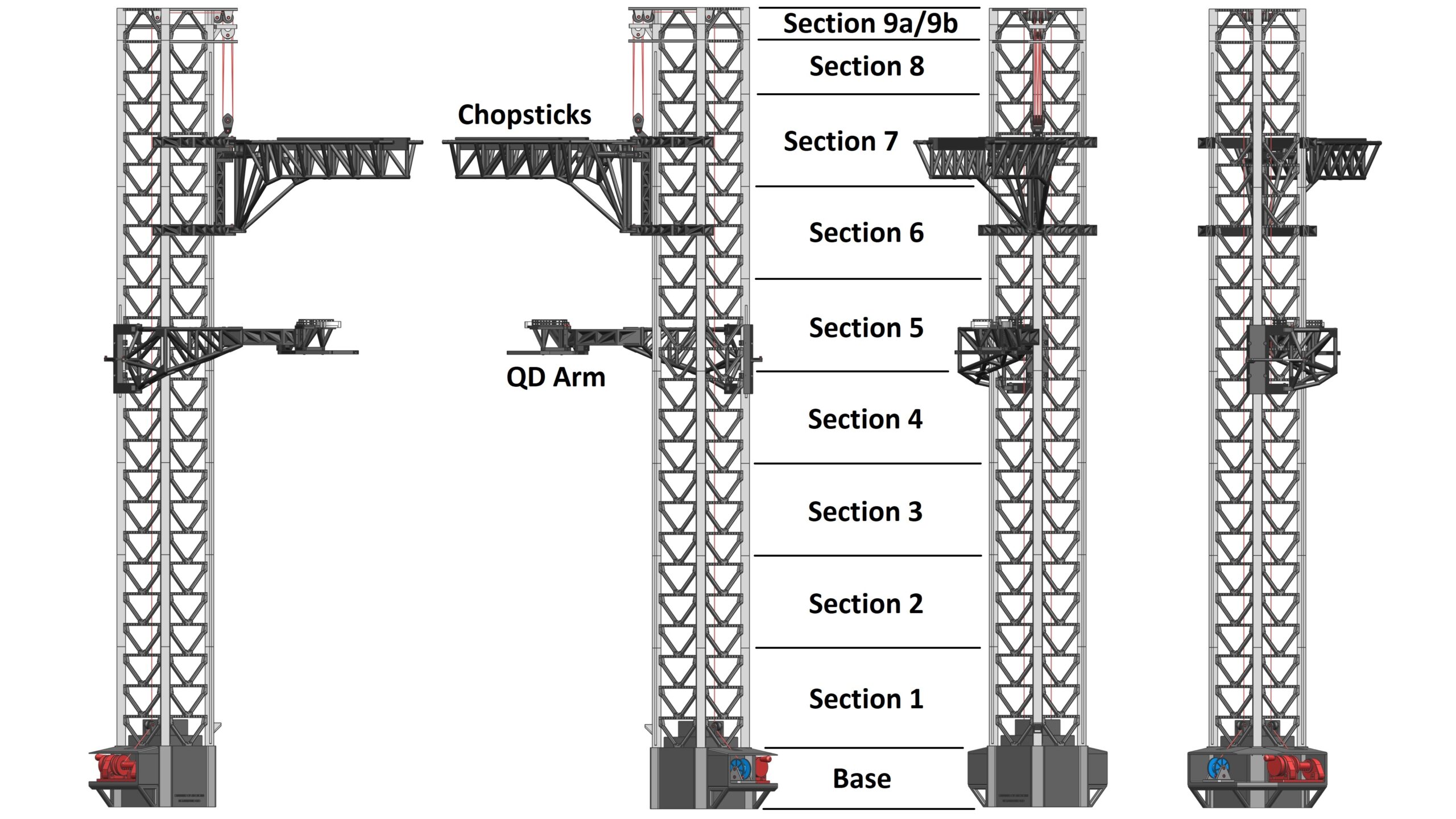
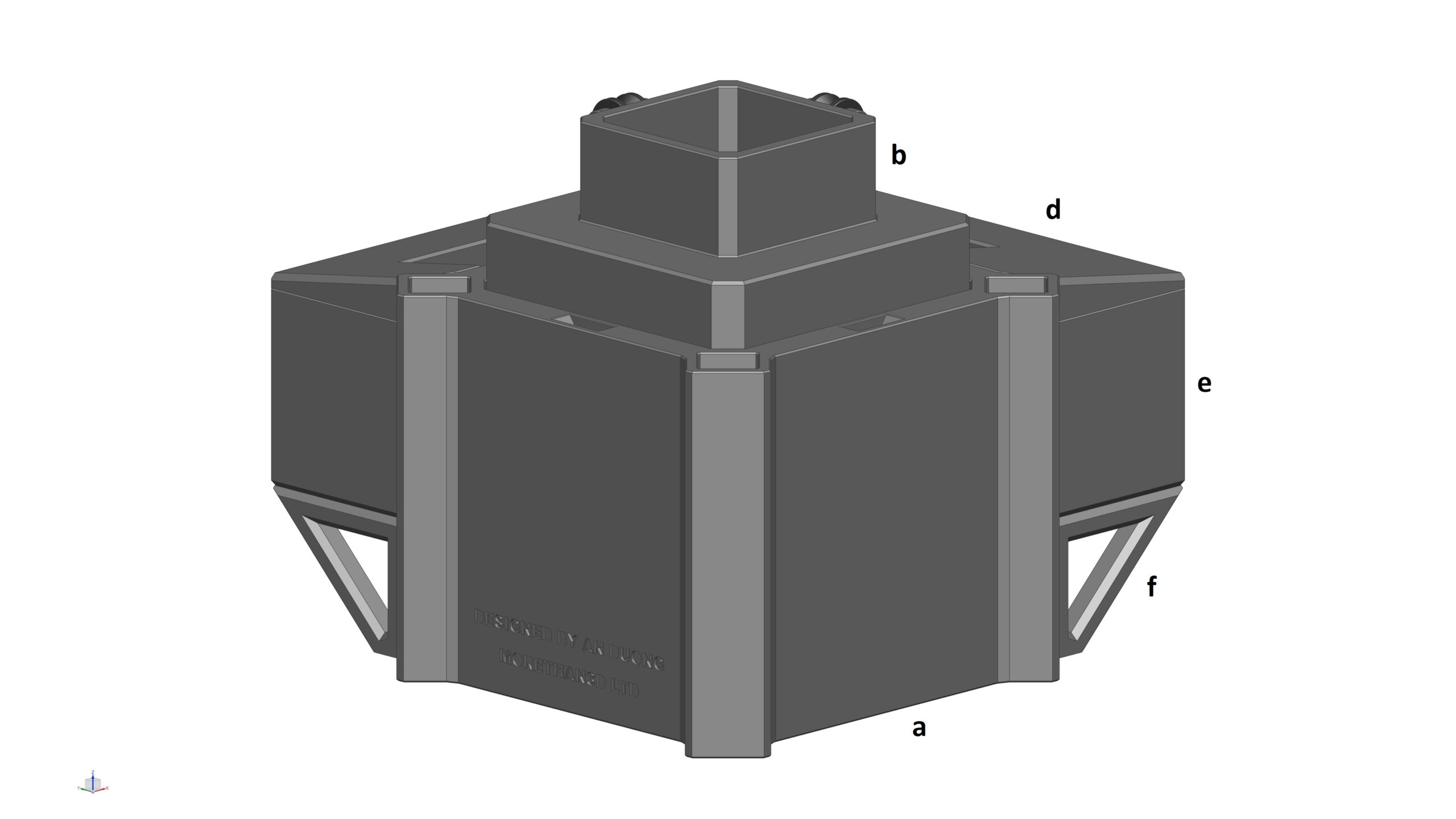
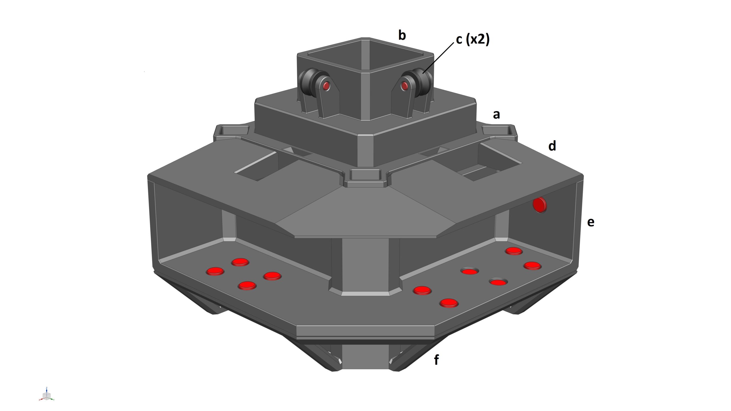
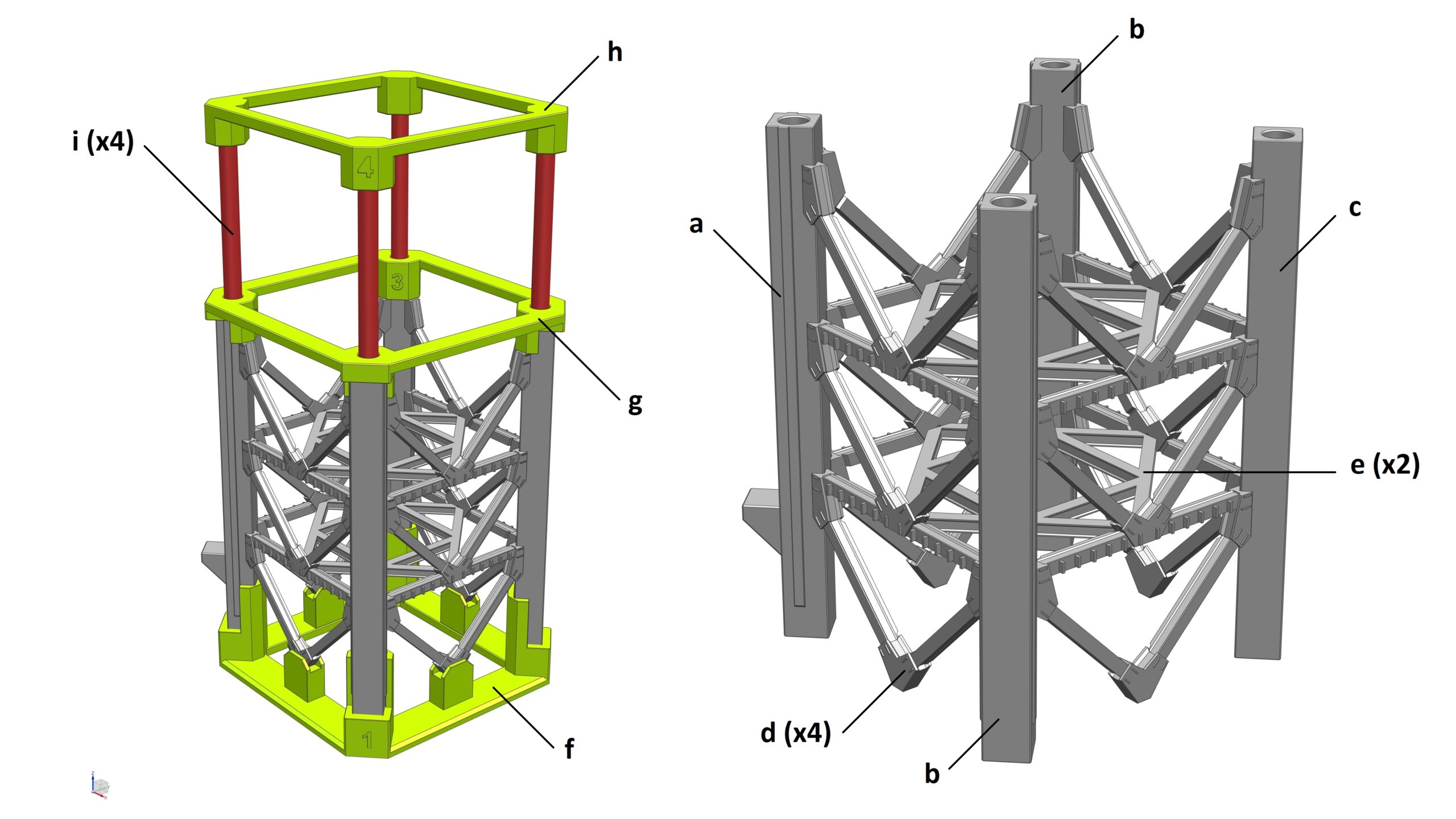
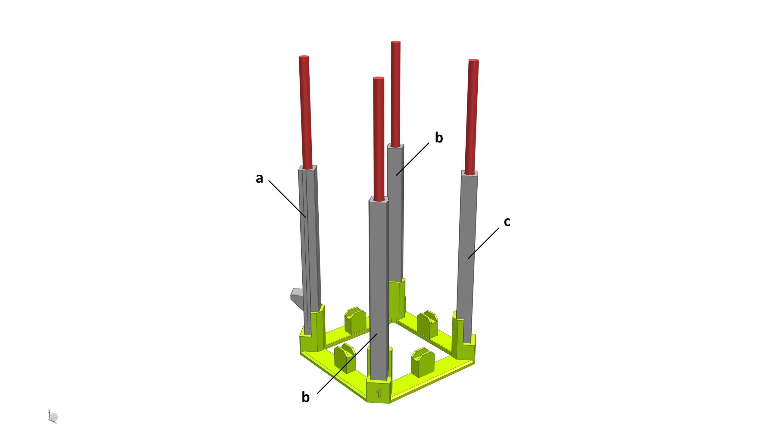
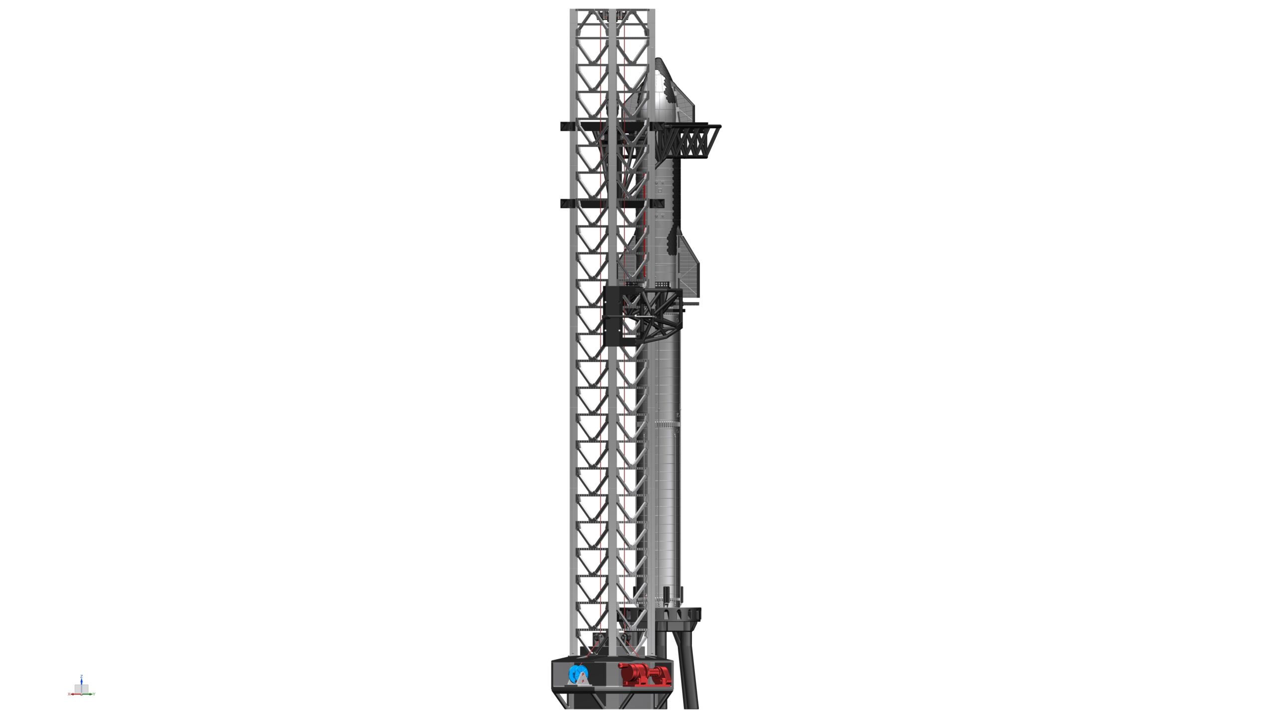
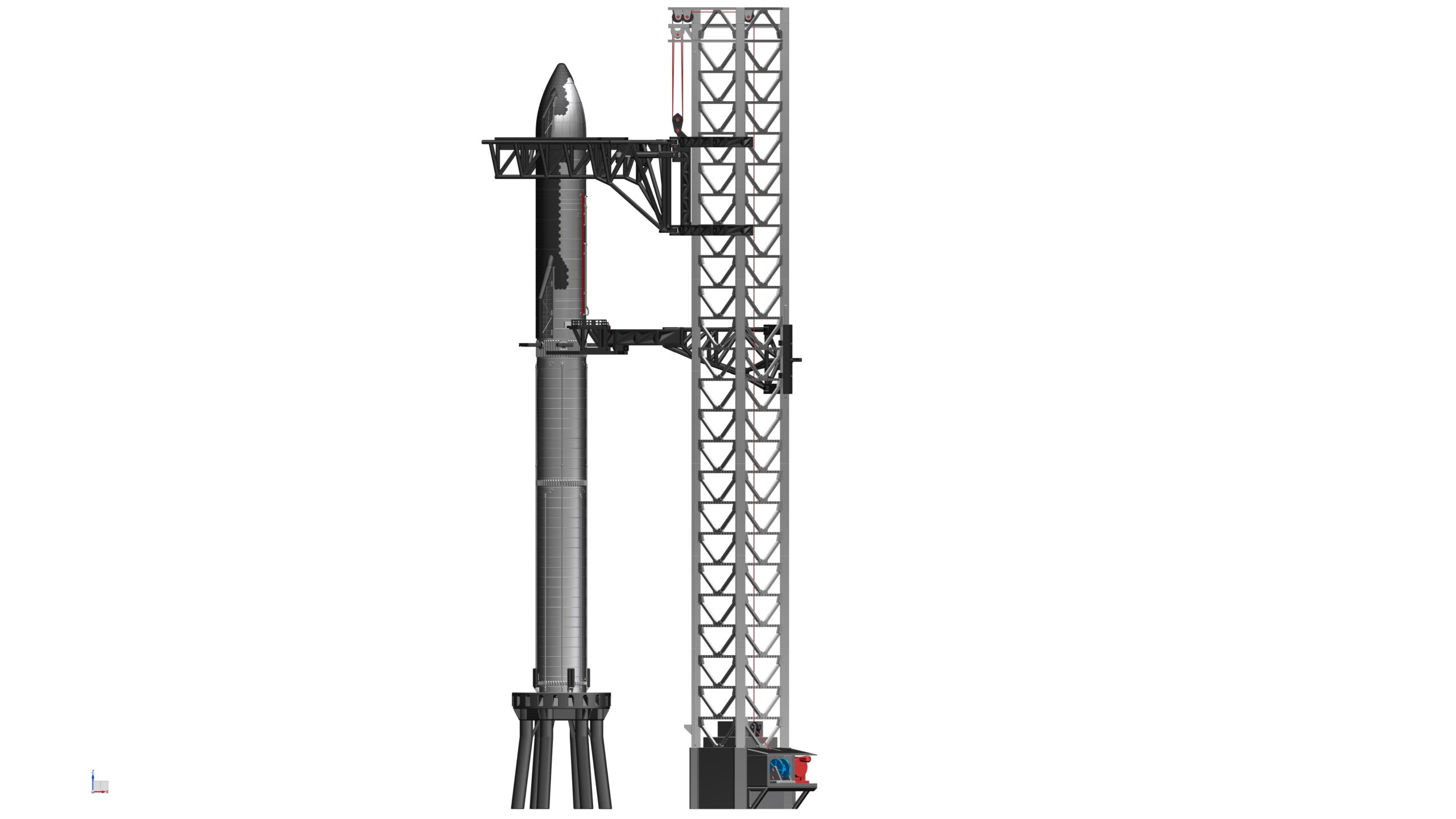
• The tower looks light grey: https://images.app.goo.gl/8hzcNzecpLsS8JoF8
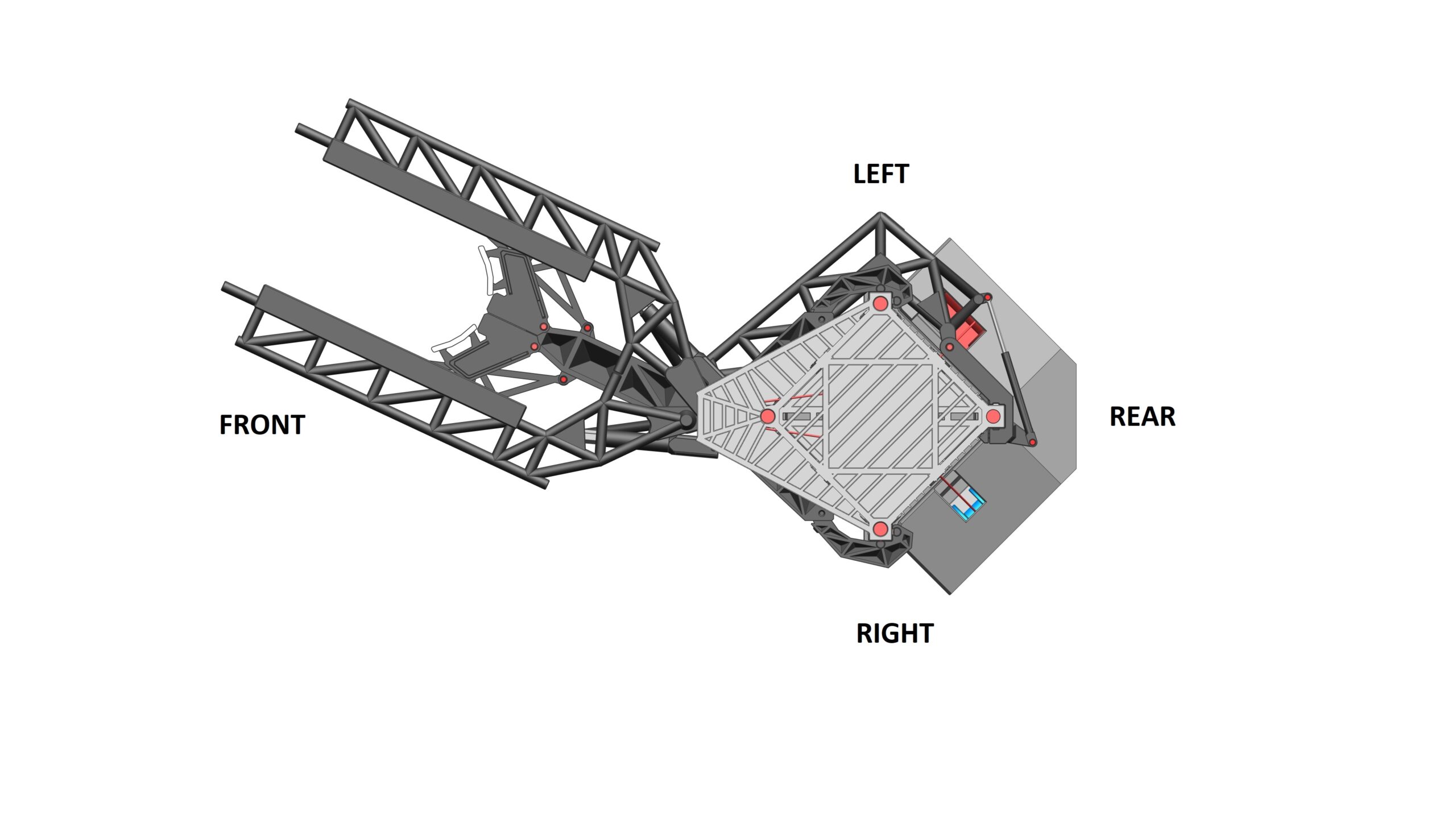
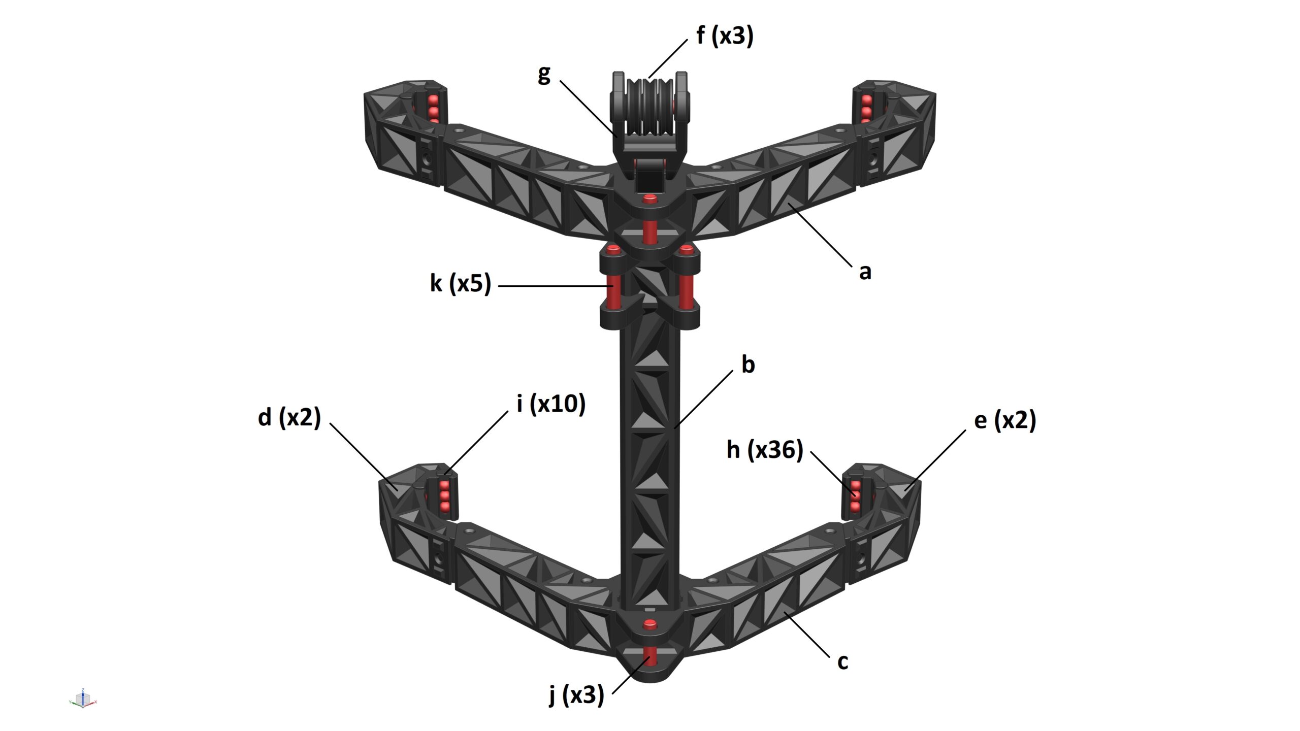
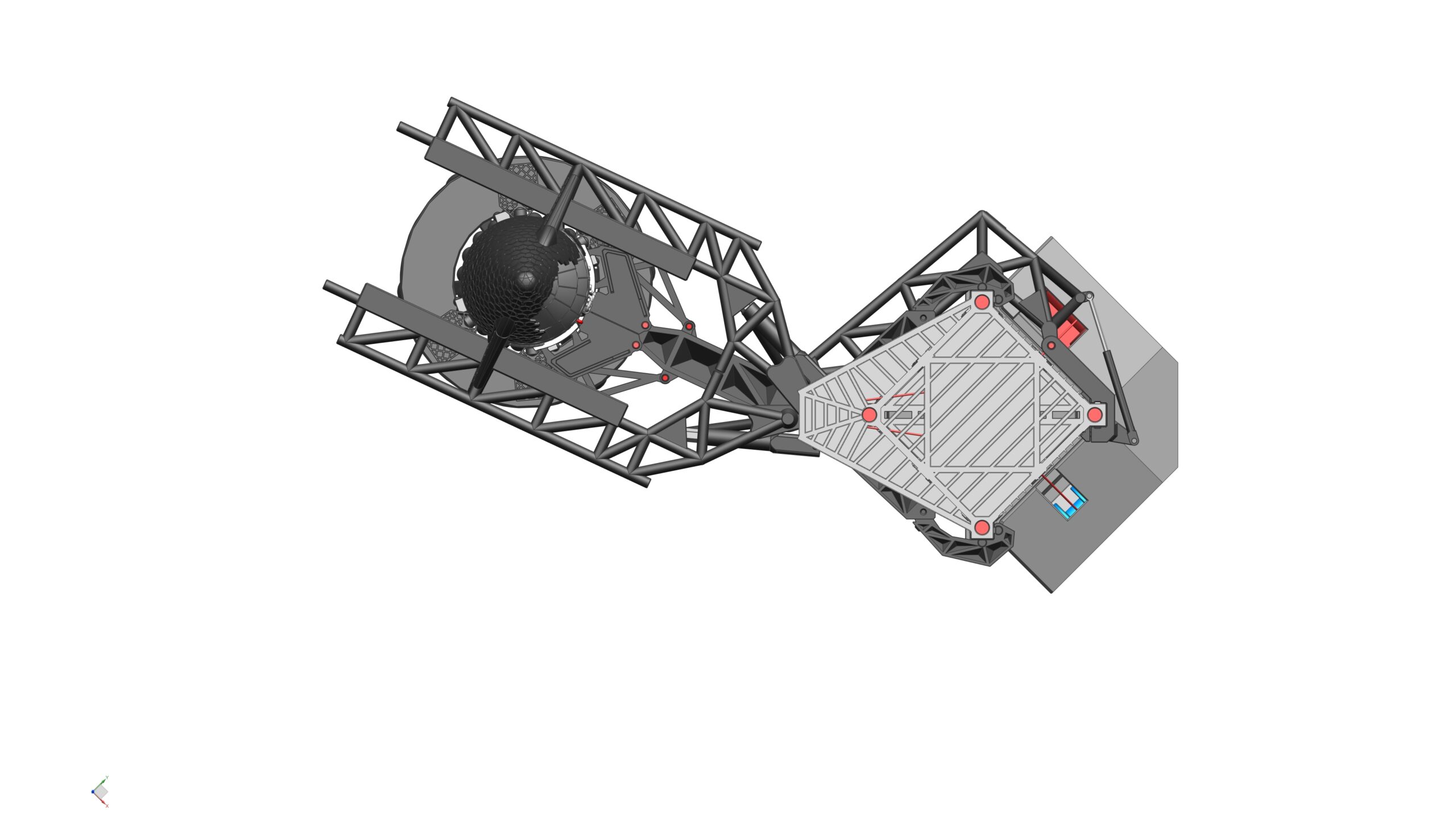
• The arms look black: https://images.app.goo.gl/J9HQN92Hpyf5PXQ49, https://images.app.goo.gl/Qzt9Yp3Zh8aVvJE18
• The gears at the top are black? https://youtu.be/qt3BrgRJL1o
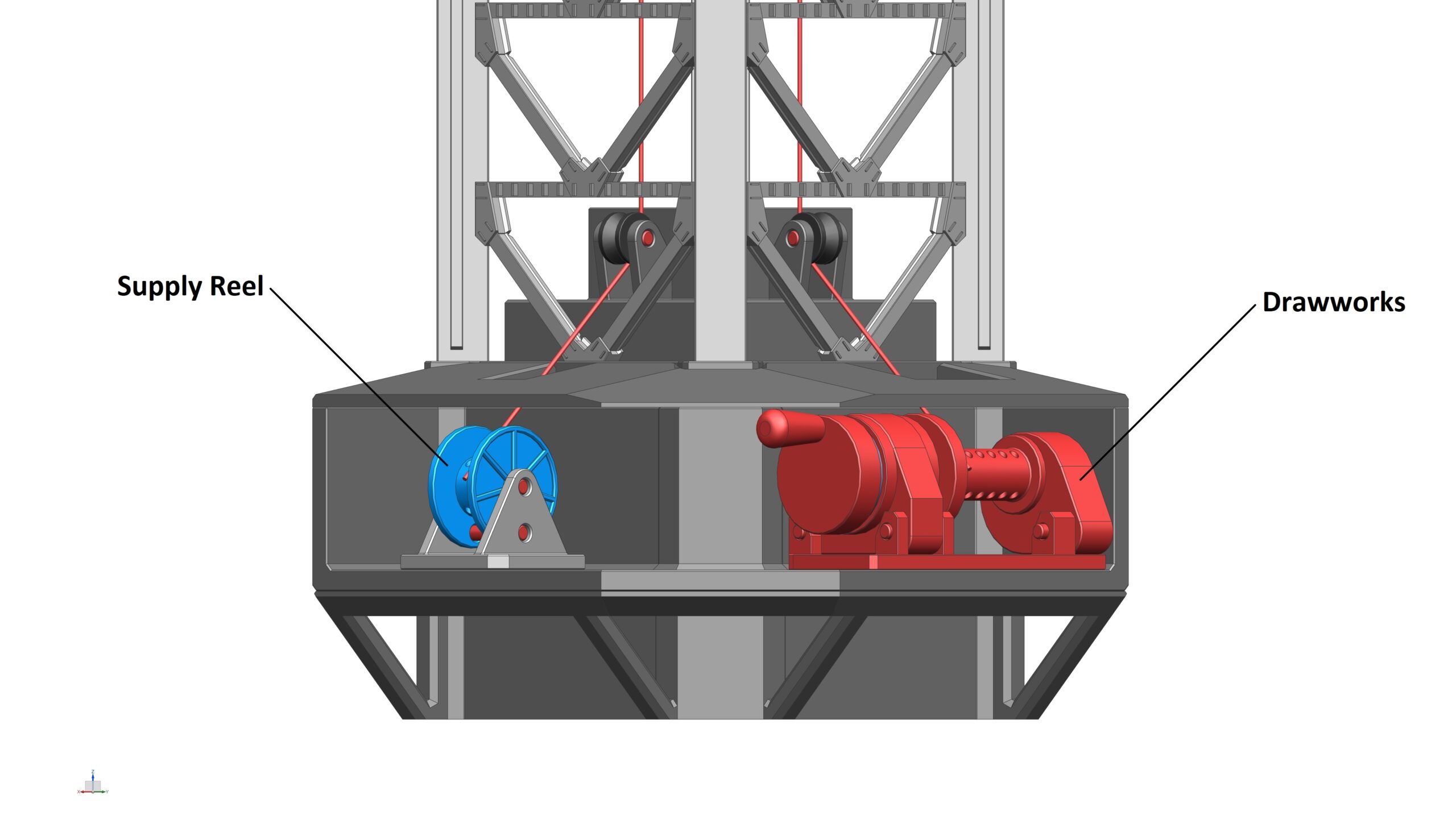
• Some part of the lift motor is red? https://youtu.be/qt3BrgRJL1o?t=436

Or please post other, clearer photos if you can find them…

4
0
Please vote & feedback on this product :)x