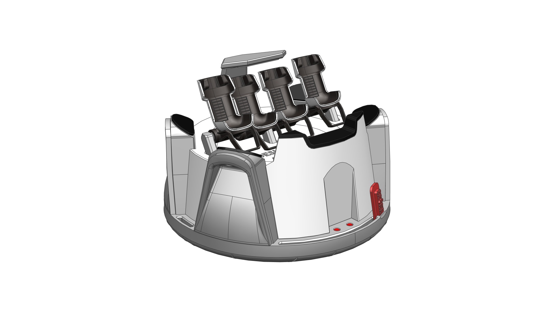
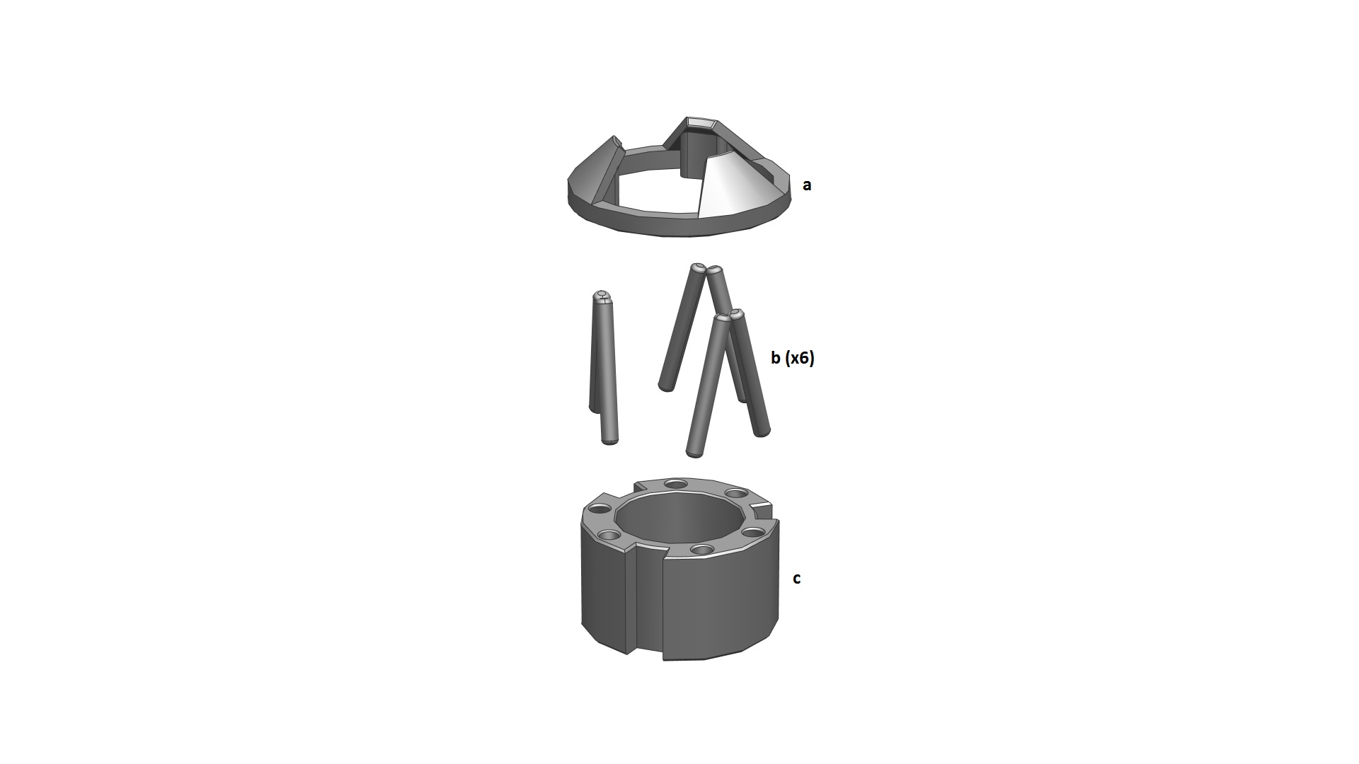
Parts required (refer to the photos below):
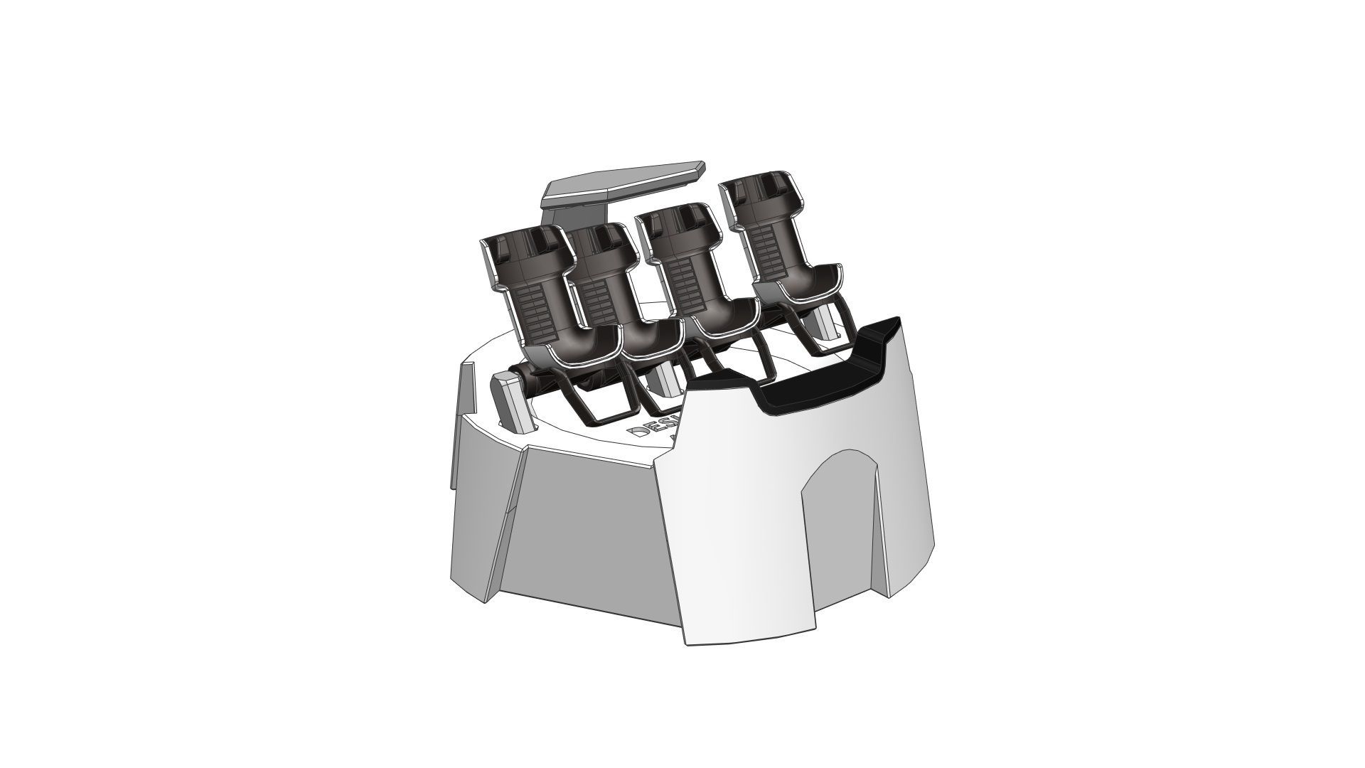
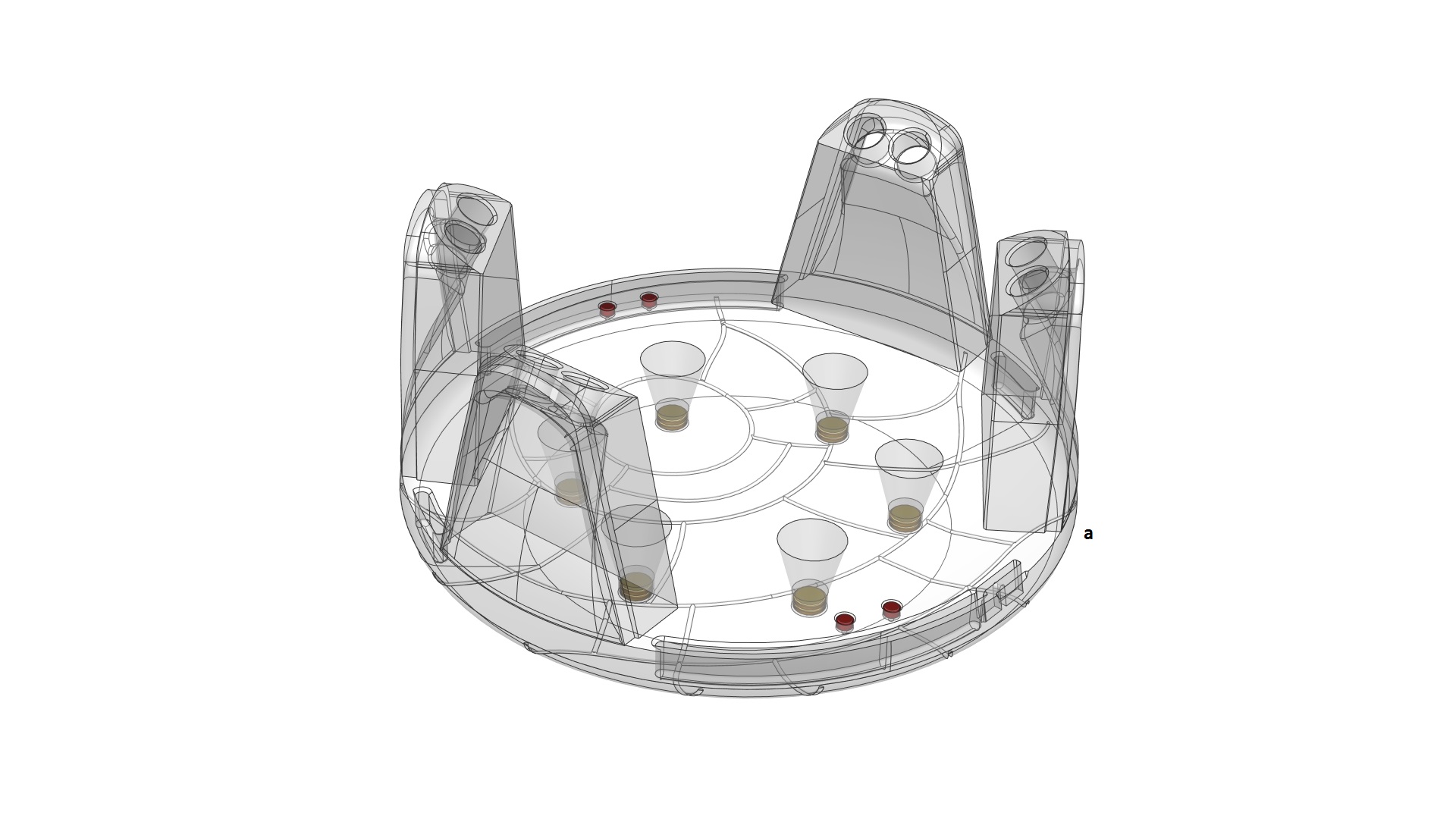
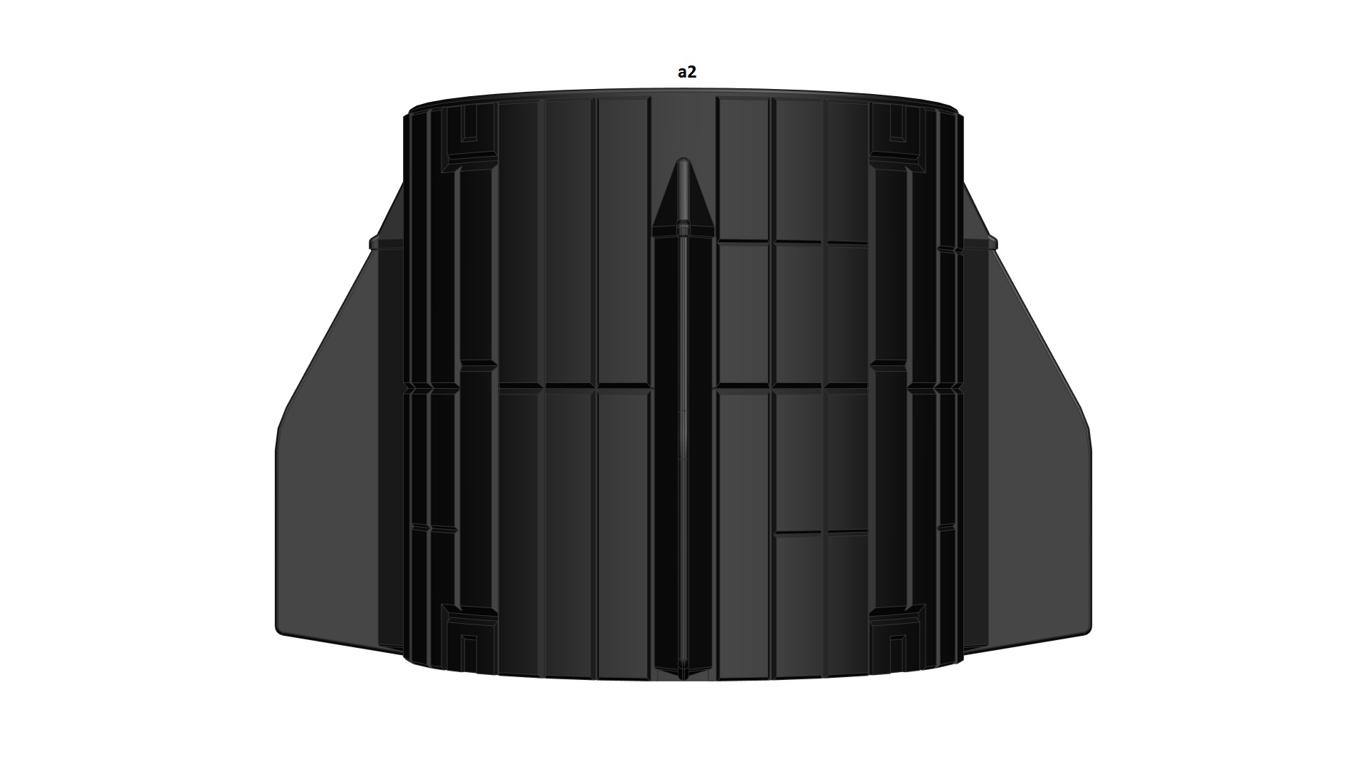
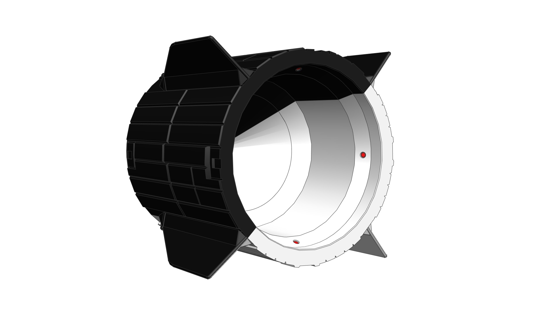
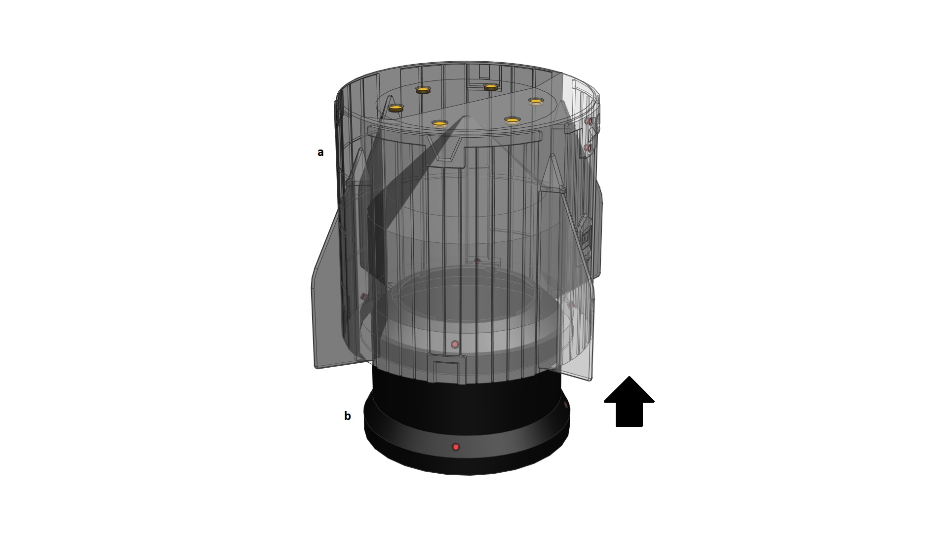
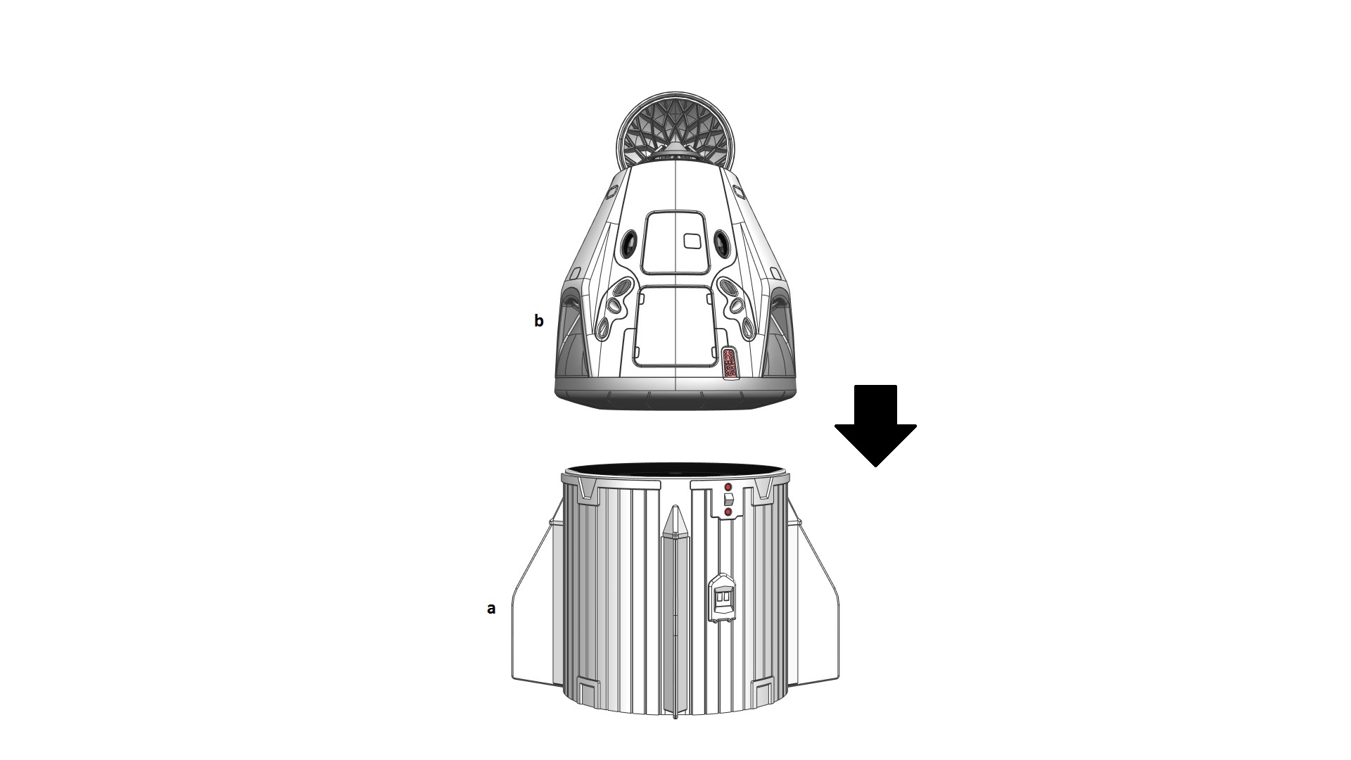
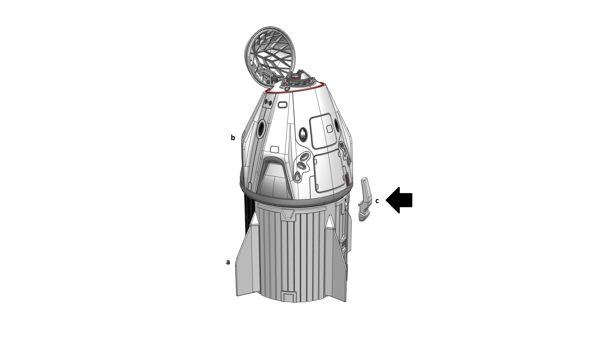
- 1x Trunk (a)*
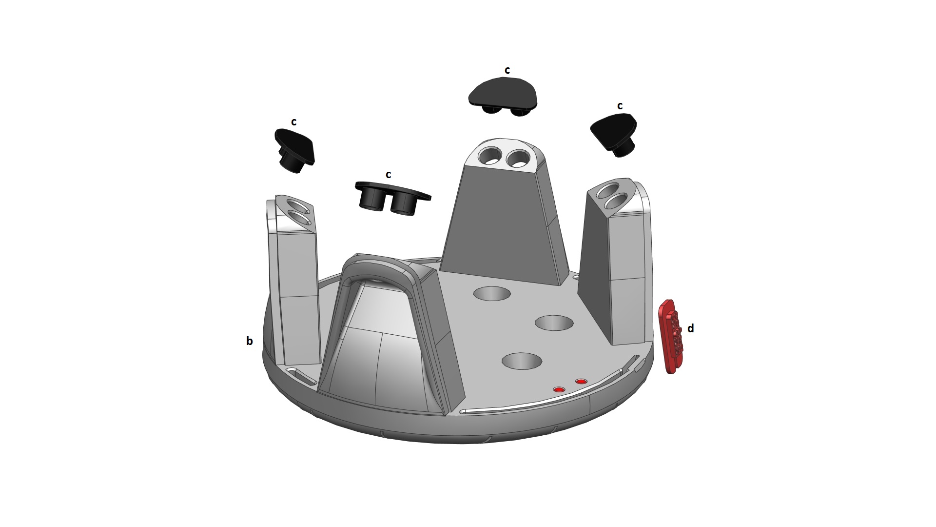
- 1x Secret Compartment (b)
- 10x Magnets (5mm dia x 3mm thick) (highlighted in RED)
- 18x Magnets (10mm dia x 2mm thick) (highlighted in ORANGE)
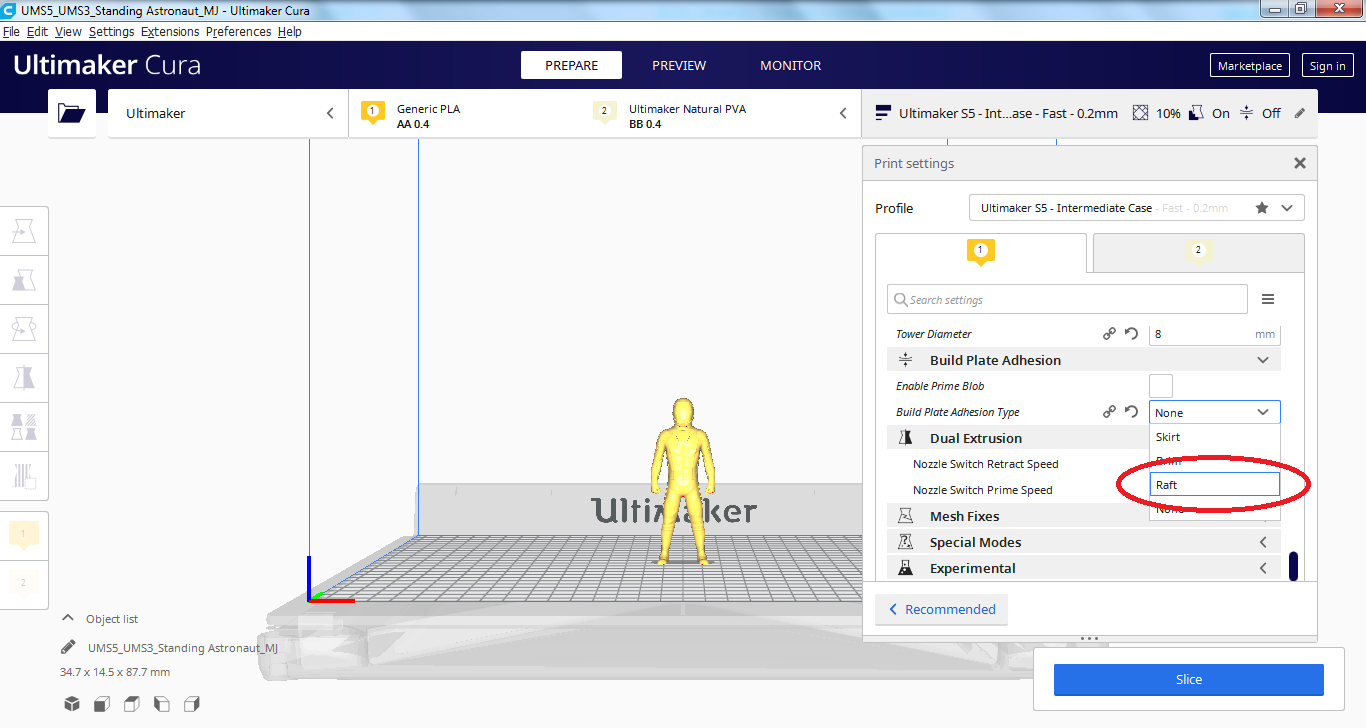
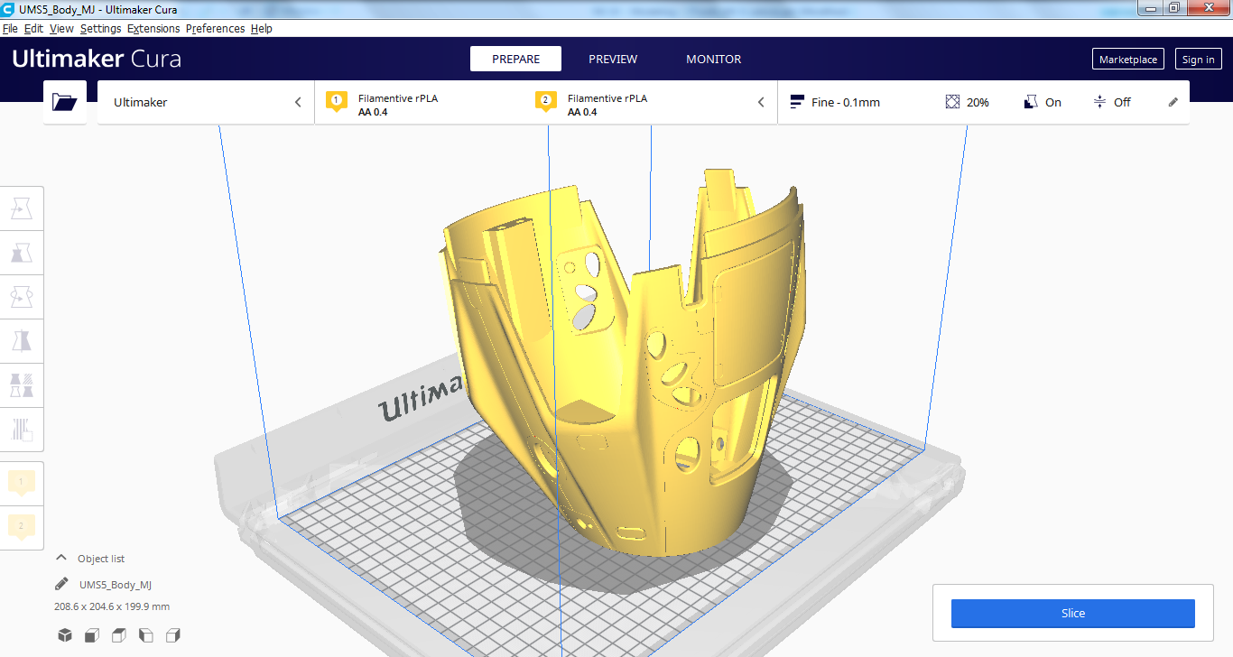
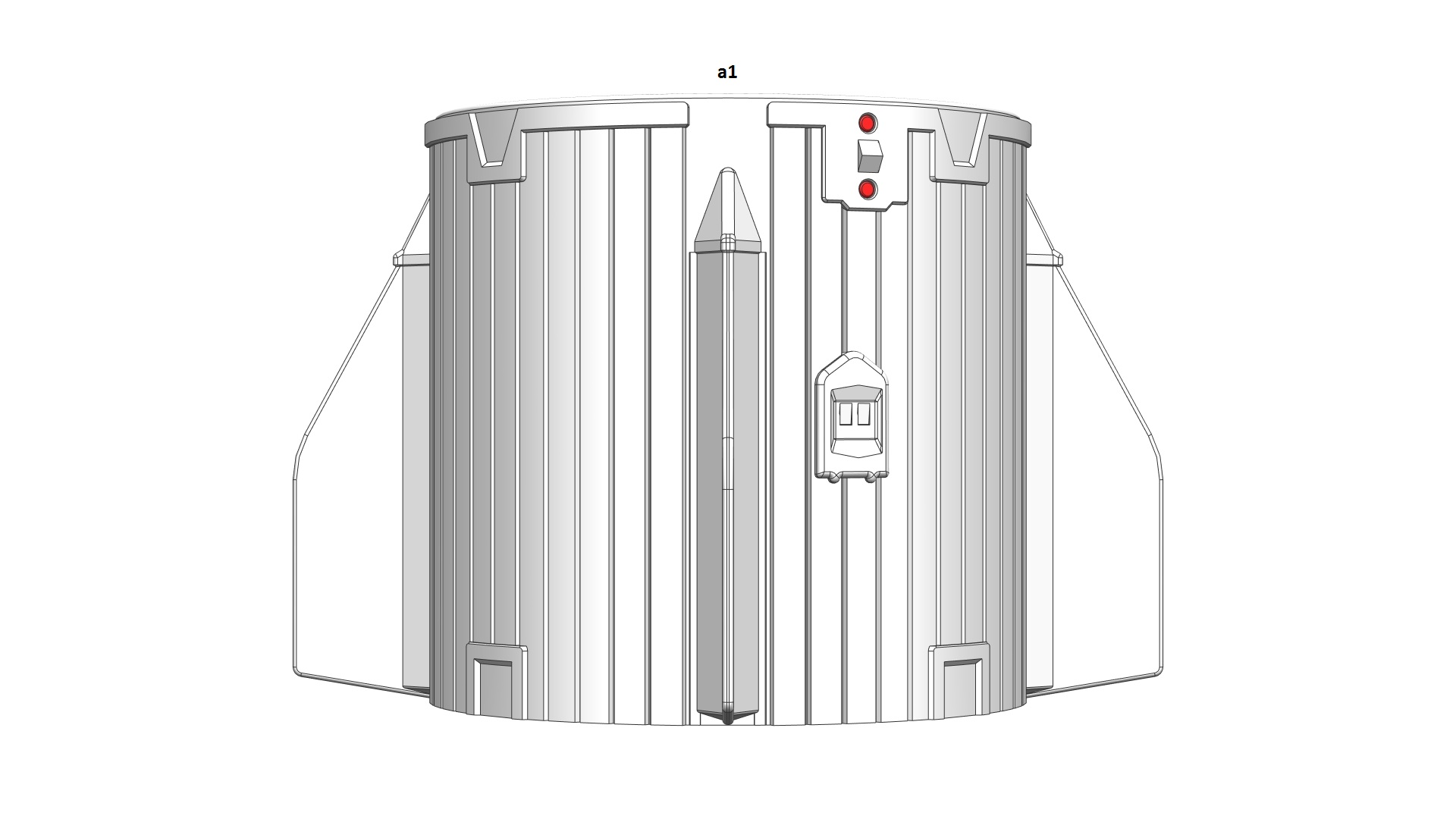
Please note: I printed both halves of the Trunk together on a dual-extrusion printer (Ultimaker S5). If you don’t have a dual-extrusion printer, you can either (1) print the whole Trunk in one colour (use the Trunk (1-piece) STL) and paint half of it with another colour OR (2) print two halves separately in two colours and glue them together. In this case, you’ll have Trunk_Front (a1) and Trunk_Rear (a2)
Assembly process:
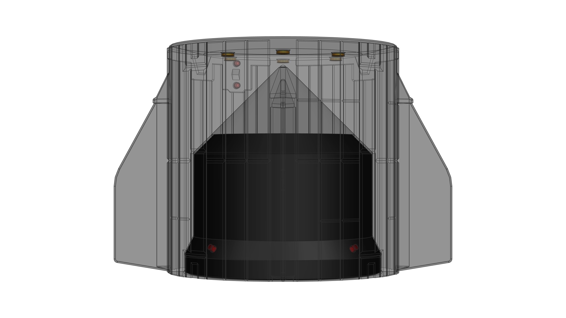
- Glue 2 magnets (5mm dia x 3mm thick) into the 2 holes located on the front side of the Trunk
- Glue 4 magnets (5mm dia x 3mm thick) into the 4 holes located on the chamfer of the Secret Compartment
- Glue 4 magnets (5mm dia x 3mm thick) into the 4 holes located on the chamfer inside the Trunk
- Glue 6 magnets (10mm dia x 2mm thick) into the 6 holes located on top of the Trunk (ensure that these magnets attract the ones previously fitted on the Heat Shield at STEP 4)
- Glue 12 magnets (10mm dia x 2mm thick) in 6 stacks of 2 into the 6 holes located inside the Secret Compartment (ensure that these magnets attract the ones previously fitted on the Heat Shield at STEP 4 when you put the bottom face of these two parts against each other)
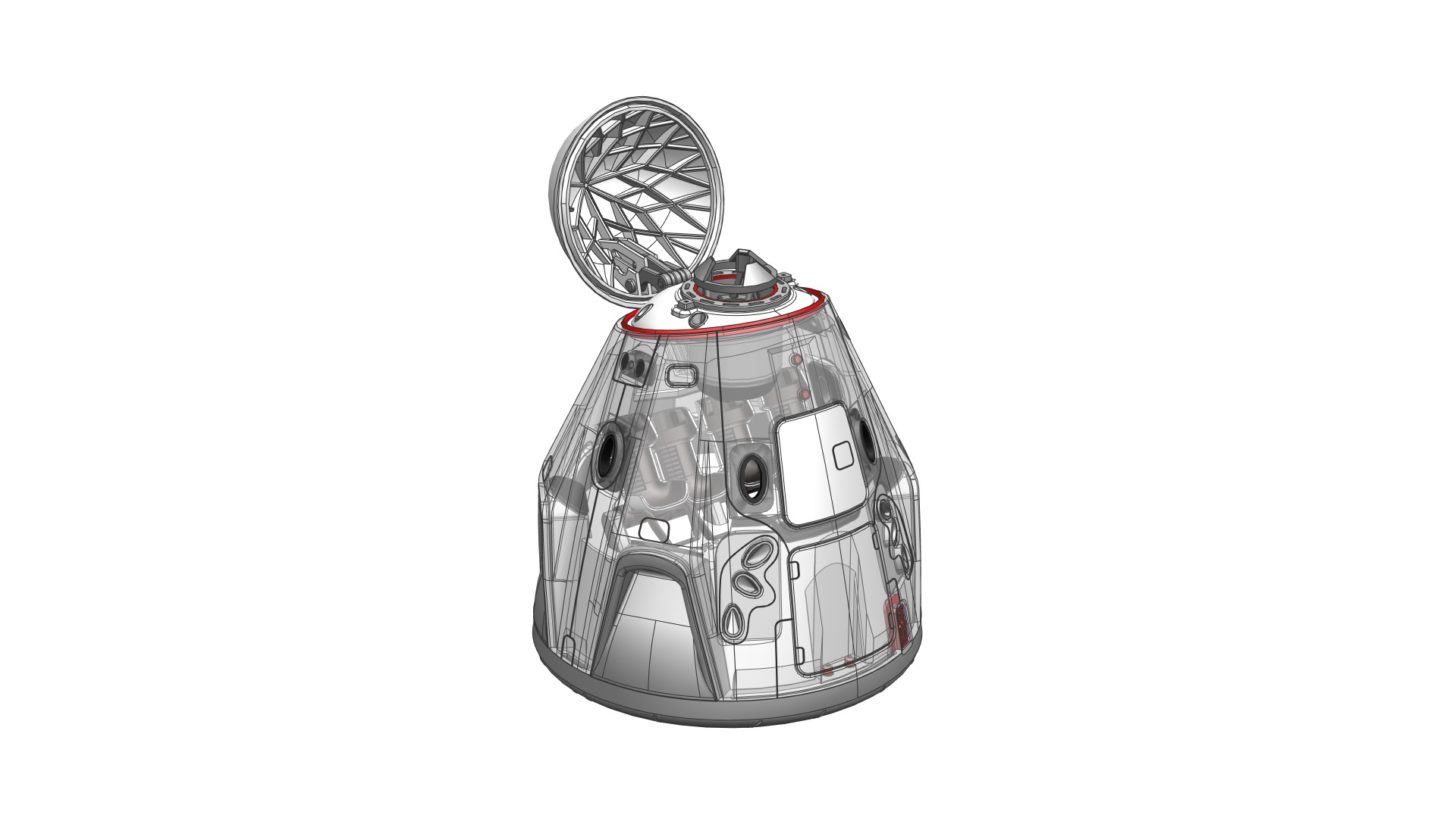
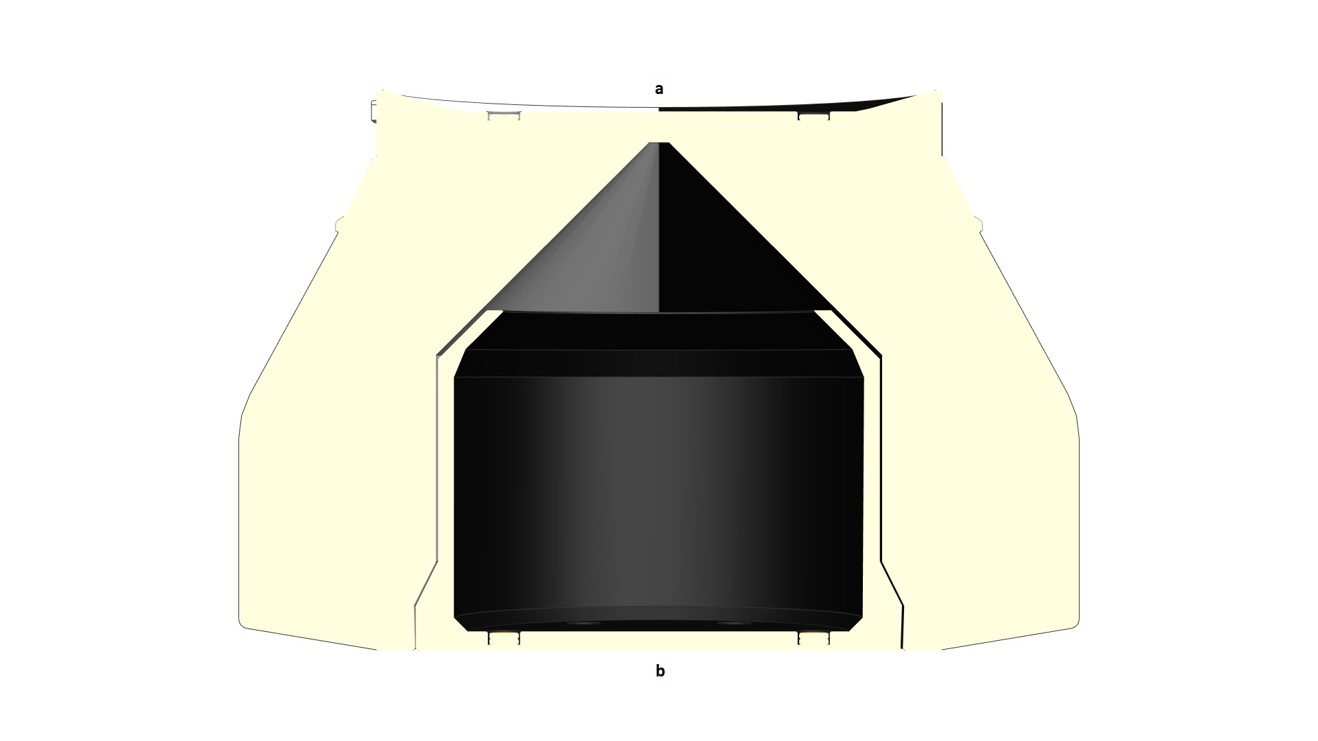
How does the Secret Compartment work?
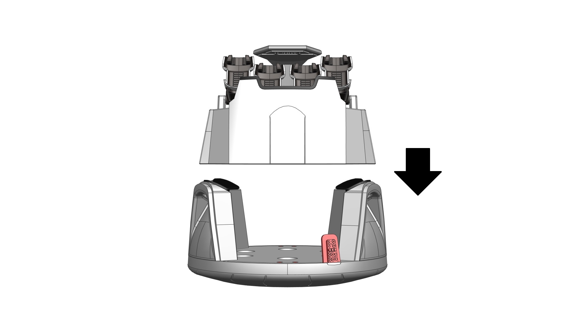
When the Secret Compartment is fitted into the Trunk, spin the bottom of this part until the 4 magnets located on its chamfer align with those located on the chamfer inside the Trunk. The Secret Compartment is now ‘locked’ and its bottom face flushes with the bottom face of the Trunk – making it impossible to open unless you know how!
To ‘unlock’ the Secret Compartment: Use the bottom of the Heat Shield – place the Heat Shield directly on the Secret Compartment (make sure that the bottom faces of these two parts are in contact. Slightly rotate the Heat Shield until you feel the magnets are aligned with those on the Secret Compartment. Now, hold the Heat Shield steadily and pull it away from the Trunk, the Secret Compartment will come out.


When it comes to soldering lighting wire on to a neodymium magnets, it is my experience and understanding that above 80 degrees centigrade, they will de-magnitize. Better to solder wire to small washer that can then be located on magnet on battery.