How to Print & Assemble The BOOSTER-S1

How to print the BOOSTER-S1

If you want to save this How-To instruction as a pdf file (and print it out later if needed), simply copy the URL of this page and paste it to https://www.printfriendly.com/ . Printfriendly will generate a printer-friendly pdf of the page with all the texts and images for you.

All of the STL files are really straight forward to print. All you need to do is load them into your slicer software (I use Cura), select your desirable settings (e.g. layer height, infill percentage, etc.) and slice the parts. I used 0.4mm nozzle and 0.2mm layer height to print large parts, and 0.25mm nozzle and 0.1mm layer height to print small parts (e.g. Raptor engines).

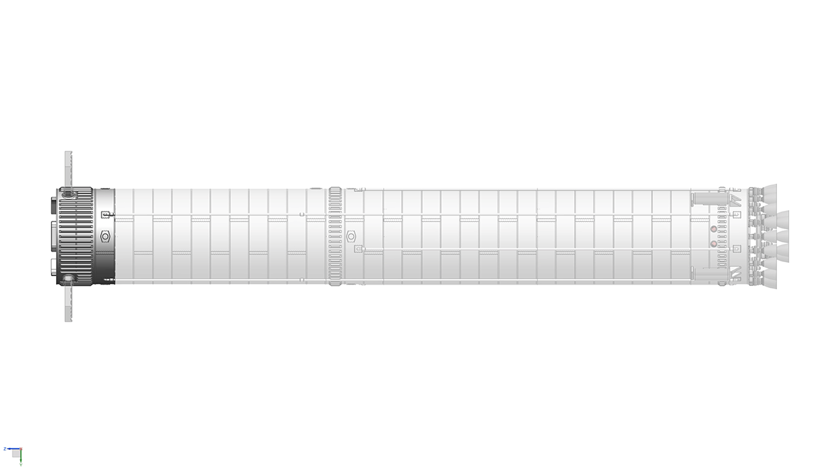
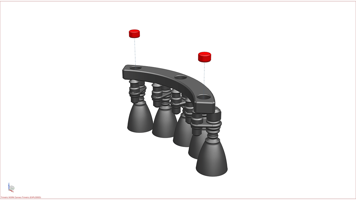
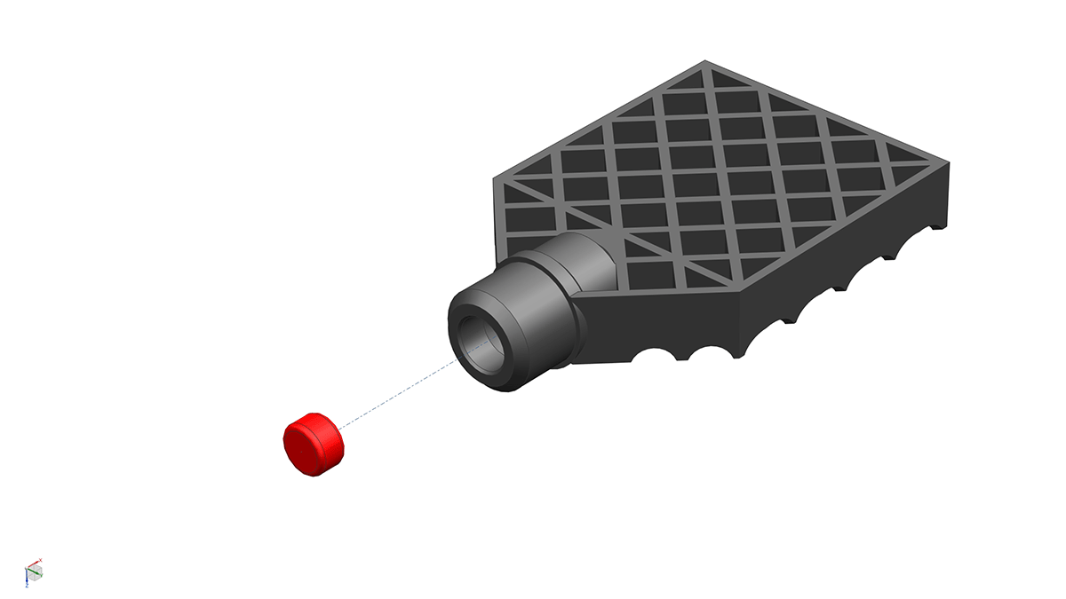
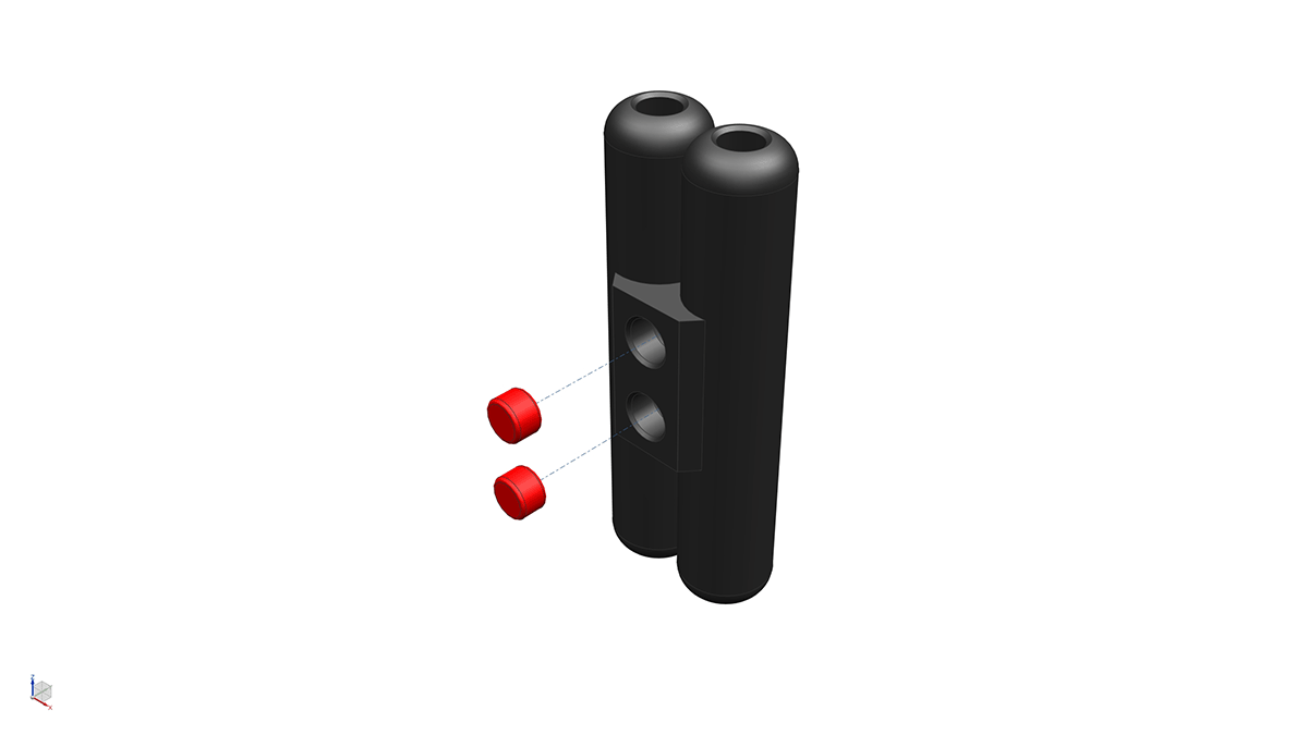
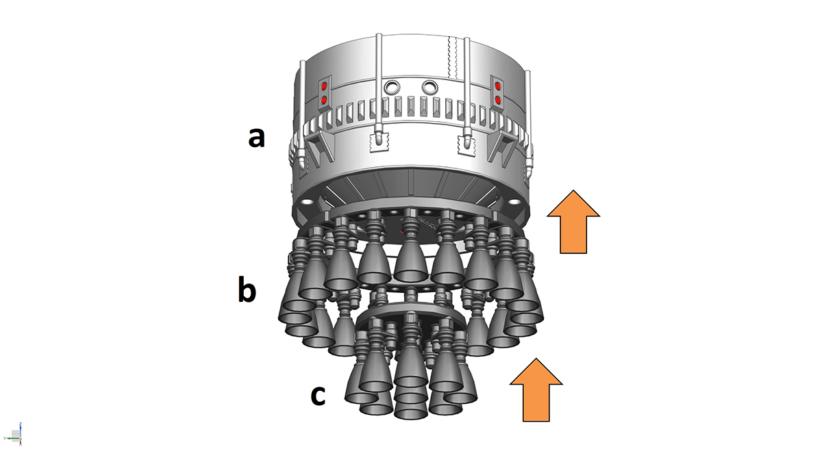
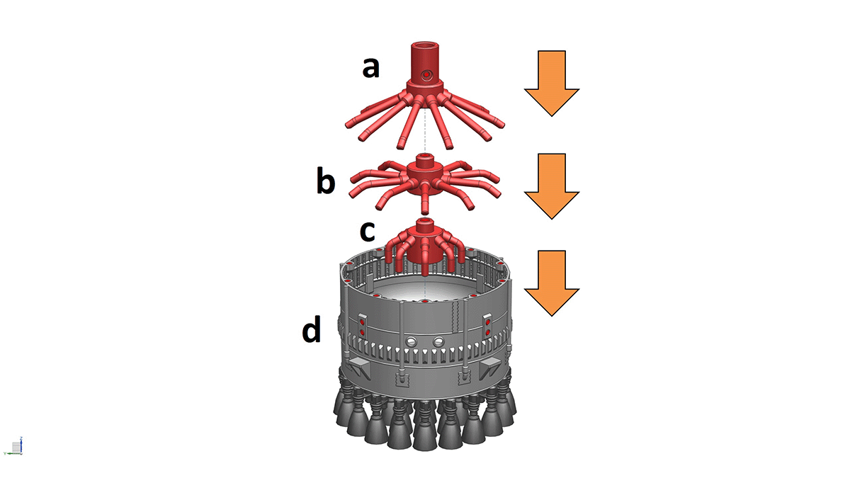
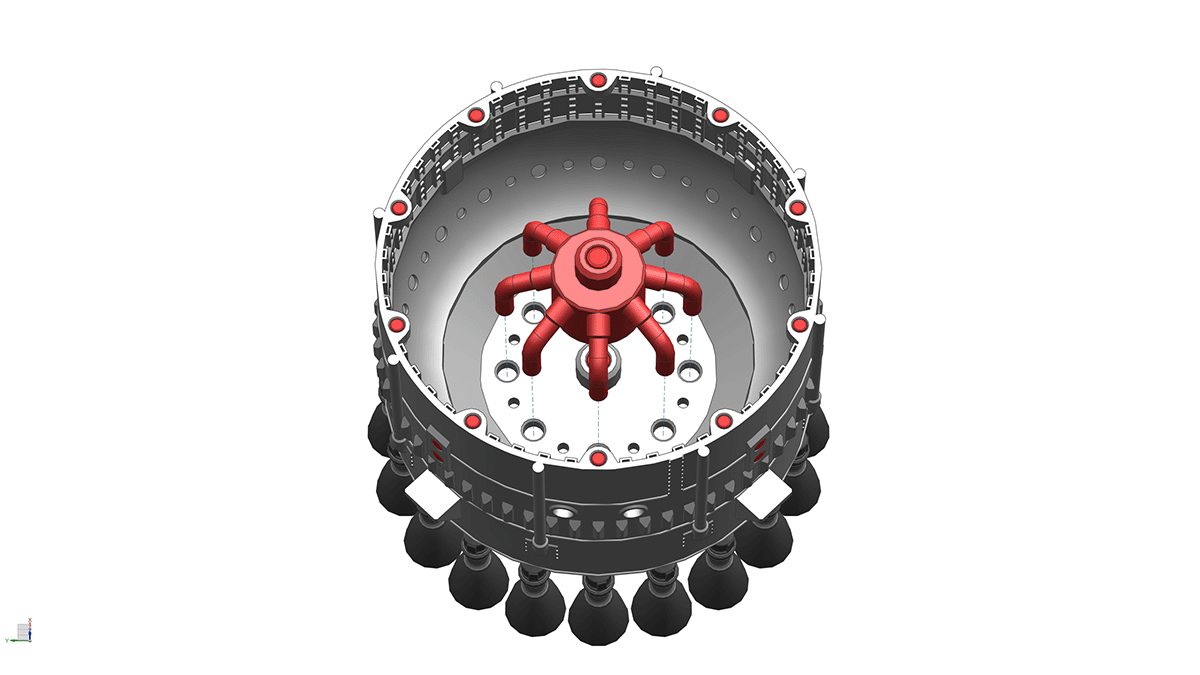
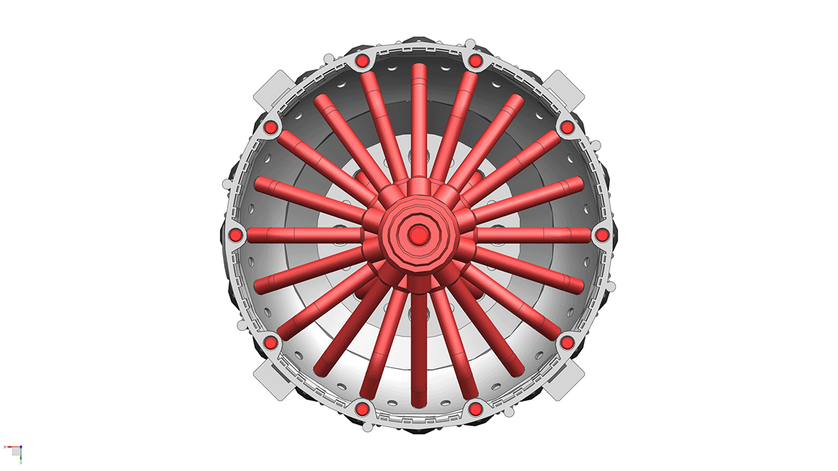
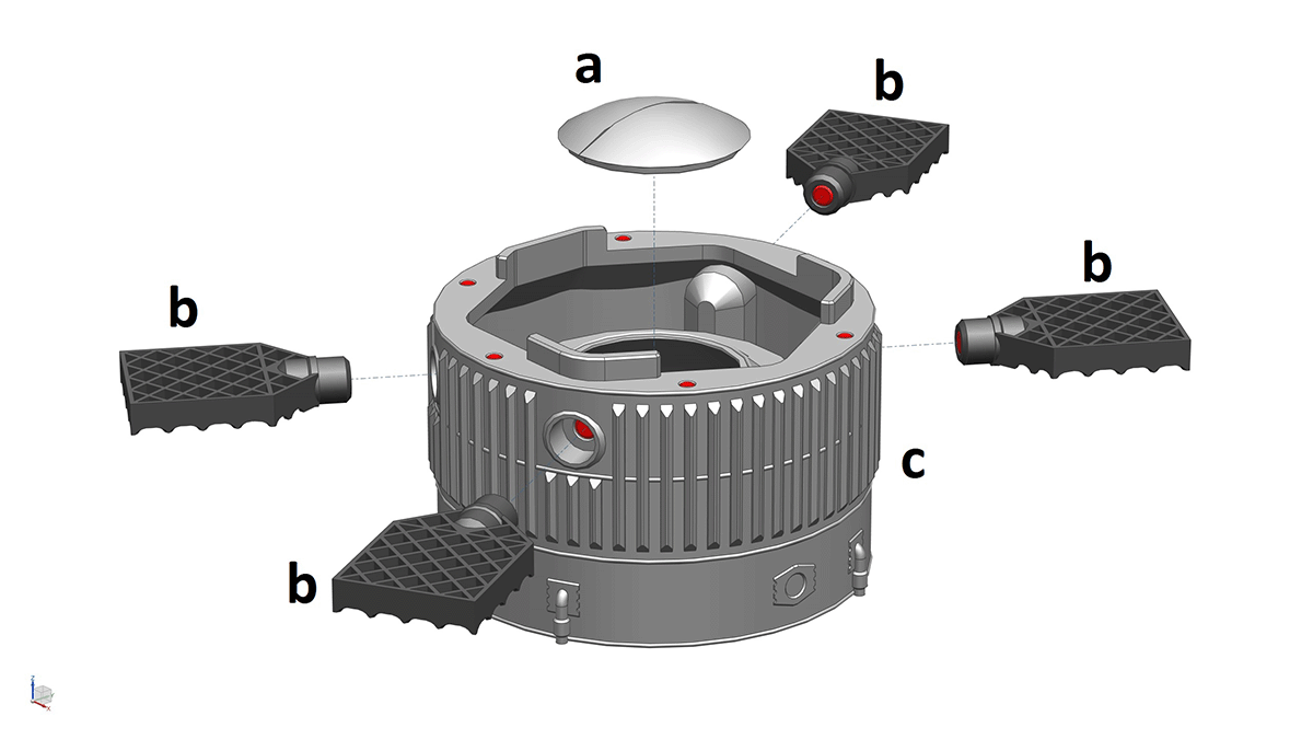
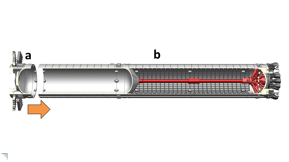
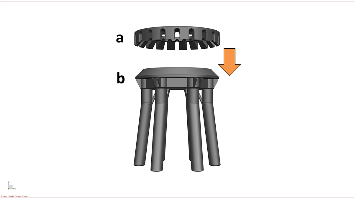
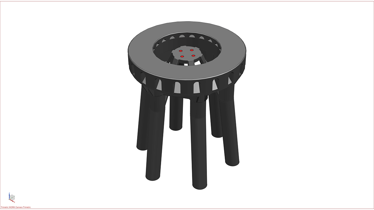
Please note: I already saved the STL for each part in the orientation I printed them on my FDM printer. Hence, when you load the STL in your slicer software, you don’t need to orientate them again, unless you want to try to print them in a different orientation.

Below are some tips.

  • All magnet holes can be printed without support regardless of their positions/orientations on the model. Please don’t generate support for these holes (unless you really need to). Otherwise, you may struggle to remove support inside the holes due to restricted access. The easiest way to stop Cura from generating support inside these magnet holes is to use support blocker to cover the holes.

  • All stiffeners (inside the LOX Tank Section) can be printed without support. In fact, most parts in this model can be printed without having to use any support at all. The only parts that you need to use support are: (1) Booster Aft Section, (2) Booster Thrust Puck, (3) Booster CH4 Distribution Pipes (Top/Mid/Bottom), (4) Booster Raptor Engines_Outer and (5) Booster COPV.

  • This Booster model is designed in such a way that allows you to assemble and disassemble the model into piece part level because almost every part is held together by magnets. However, if you prefer to glue everything (or some parts together), that’s also fine – but please be aware that if you do, it may be difficult to update the model later on. In addition, since most parts are cylindrical; you may find it a bit challenging to figure out how to rotate each segment correctly whilst stacking them together. I deliberately did not incorporate any features (e.g. marks, arrows, etc.) to help you orient the parts easier because I want to make it a fun exercise should you want to challenge your kids to put together a Starship.

  • There is an STL in folder ‘STEP 01’ called ‘Booster Assembly_1-96_v1.stl’. If you load this file, you’ll see the fully assembled Booster-S1 model. This will help you understand where each and every part is fitted on the model.

  • This model is designed at 1:96 scale and I highly recommend you to print at this scale to achieve the highest quality. However, if you decided to print it at a different scale, please be aware that the magnets I selected for this model will no longer fit and you will have to glue the parts together.

How to assemble the BOOSTER-S1

So now you’ve got all your parts printed? Great! Let’s assemble the model!

I’ll take you through the assembly process step by step but before that, you need to purchase some items:

  • 5mm dia x 3mm thick N42 Neodymium magnets (LINK) | Qty: 50-off
  • 3mm dia x 2mm thick N42 Neodymium (LINK) | Qty: 123-off
  • Super glue (LINK) | Qty: 1 bottle

STEP 1: ‘Dry’ assemble the model

At this step, all I want you to do is try to stack all the parts together to get a good understanding of where they are located. Because there are a lot of magnets you need to fit during the assembly process, doing this first step will give you an idea of how to fit the magnets in each part correctly. Please use the ‘Booster Assembly_1-96_v1.stl’ and the photos below if required.

STEP 2: Assemble the Booster Aft Section

Parts required (refer to the photos below)

  • 1x Booster Aft Section_1-96_v1
  • 18x Magnets (3mm dia x 2mm thick) (highlighted in red)
  • 8x Magnets (5mm dia x 3mm thick) (highlighted in red)

Assembly process

  1. Glue 18x magnets (3mm dia x 2mm thick) into their pockets on the top and side of the Booster Aft Section
  2. Glue 8x magnets (5mm dia x 3mm thick) into their pockets on the bottom of the Booster Aft Section. Use the optional 4 holes if extra magnetic force is required

STEP 3a: Assemble the Booster Thrust Puck

Parts required (refer to the photos below)

  • 1x Booster Thrust Puck_1-96_v1
  • 5x Magnets (5mm dia x 3mm thick) (highlighted in red)

Assembly process:

  1. Glue 4x magnets (5mm dia x 3mm thick) into their locations on the bottom of the Booster Thrust Puck
  2. Glue 1x magnets (5mm dia x 3mm thick) into its location on the top of the Booster Thrust Puck

STEP 3b: Assemble the Booster Thrust Puck to Booster Aft Section

Parts required (refer to the photos below)

  • 1x Booster Thrust Puck_1-96_v1 from STEP 3a (a)
  • 1x Booster Aft Section from STEP 2 (b)

Assembly process

  1. Glue the Booster Thrust Puck to the bottom of the Booster Aft Section. Use the cut-out slots on the Thrust Puck for alignment.

STEP 4: Assemble the Booster LOX Tank_Bottom Section

Parts required (refer to the photos below)

  • 1x Booster LOX Tank_Bottom Section_1-96_v1
  • 20x Magnets (3mm dia x 2mm thick) (highlighted in red)

Assembly process

  1. Glue 20x magnets (3mm dia x 2mm thick) into their locations on the top and bottom of the Booster LOX Tank_Bottom Section

STEP 5: Assemble the Booster LOX Tank_Top Section

Parts required (refer to the photos below)

  • 1x Booster LOX Tank_Top Section_1-96_v1
  • 20x Magnets (3mm dia x 2mm thick) (highlighted in RED)

Assembly process

  1. Glue 20x magnets (3mm dia x 2mm thick) into their locations on the top and bottom of the Booster LOX Tank_Top Section

STEP 6: Assemble the Booster Common Dome Section

Parts required (refer to the photos below)

  • 1x Booster Common Dome Section_1-96_v1
  • 20x Magnets (3mm dia x 2mm thick) (highlighted in RED)

Assembly process

  1. Glue 20x magnets (3mm dia x 2mm thick) into their locations on the top and bottom of the Booster Common Dome Section

STEP 7: Assemble the Booster CH4 Tank Section

Parts required (refer to the photos below)

  • 1x Booster CH4 Tank Section_1-96_v1
  • 20x Magnets (3mm dia x 2mm thick) (highlighted in red)

Assembly process

  1. Glue 20x magnets (3mm dia x 2mm thick) into their locations on the top and bottom of the Booster CH4 Tank Section

STEP 8: Assemble the Booster Interstage Section

Parts required (refer to the photos below)

  • 1x Booster Interstage Section_1-96_v1
  • 16x Magnets (3mm dia x 2mm thick) (highlighted in red)
  • 4x Magnets (5mm dia x 3mm thick) (highlighted in red)

Assembly process:

  1. Glue 16x magnets (3mm dia x 2mm thick) into their locations on the top and bottom of the Booster Interstage Section
  2. Glue 4x magnets (5mm dia x 3mm thick) into their locations on the side pockets of the Booster Interstage Section

STEP 9a: Assemble the Raptor Engine Assembly

Parts required (refer to the photos below)

  • 1x Booster Raptor Engines_Inner_1-96_v1
  • 4x Booster Raptor Engines_Outer_1-96_v1
  • 12x Magnet (5mm dia x 3mm thick) (highlighted in red)

Assembly process

  1. Glue 4x magnets (5mm dia x 3mm thick) into their locations on the Booster Raptor Engines_Inner
  2. Glue 2x magnets (5mm dia x 3mm thick) into their locations on each of the Booster Raptor Engines_Outer. Use the optional hole if extra magnetic force is required

STEP 9b: Assemble Booster Grid Fin and COPV

Parts required (refer to the photos below)

  • 4x Booster Grid Fin_1-96_v1
  • 4x Booster COPV Bracket_1-96_v1 (a)
  • 4x Booster COPV_1-96_v1 (b)
  • 4x Magnet (5mm dia x 3mm thick) (highlighted in red)
  • 8x Magnet (3mm dia x 2mm thick) (highlighted in red)

Assembly process

  1. Glue 4x magnets (5mm dia x 3mm thick) into its location on each Booster Grid Fin
  2. Glue 2x magnets (3mm dia x 2mm thick) into their locations on each of the Booster COPV
  3. Glue a COPV Bracket (a) on the top of each Booster COPV (b)

STEP 10: Install Raptor Engines to Booster Aft Section

Parts required (refer to the photos below)

  • 1x Booster Aft Section from STEP 3b (a)
  • 4x Booster Raptor Engines_Outer from STEP 9a (b)
  • 1x Booster Raptor Engines_Inner from STEP 9a (b)

Assembly process

  1. Simply snap all Booster Raptor Engines segments to the bottom of the Booster Aft Section.

STEP 11: Install CH4 plumbing to Booster Aft Section

Parts required (refer to the photos below)

  • 1x Booster CH4 Distribution Pipes_Top_1-91_v1 (a)
  • 1x Booster CH4 Distribution Pipes_Mid_1-91_v1 (b)
  • 1x Booster CH4 Distribution Pipes_Bottom_1-91_v1 (c)
  • 1x Sub-assembly from STEP 10 (d)
  • 6x Magnets (5mm dia x 3mm thick) (highlighted in red)
  • 1x Magnet (3mm dia x 2mm thick) (highlighted in red)

Assembly process

  1. Glue 2x magnets (5mm dia x 3mm thick) into the holes on both sides of each CH4 Distribution Pipes segment
  2. Glue 1x magnets (3mm dia x 2mm thick) into the hole on the side of the Booster CH4 Distribution Pipes_Top (a)
  3. Install all the Booster CH4 Distribution Pipes to the Booster Aft Section. Ensure that all 8 pipes on the Booster CH4 Distribution Pipes_Bottom are aligned and go into the holes on the top face of the Booster Thrust Puck
  4. Finally, rotate each the Booster CH4 Distribution Pipes_Top & Mid so that all the pipes are all equally spread out.

STEP 12a: Stack Booster LOX Tank Section

Parts required (refer to the photos below)

  • 1x Booster LOX Tank_Top from STEP 5 (a)
  • 1x Booster LOX Tank_Bottom from STEP 4 (b)
  • 1x Sub-assembly from STEP 11 (c)

Assembly process

  1. Snap the Booster LOX Tank_Top & Bottom sections on top of Booster Aft section. Use the external pipes for alignment.

STEP 12b: Install CH4 Downcomer

Parts required (refer to the photos below)

  • 2x Booster CH4 Downcomer Pipe_1-96_v1 (a)
  • 1x Booster CH4 Downcomer Joint_1-96_v1 (b)
  • 1x Sub-assembly from STEP 12a
  • 6x Magnet (5mm dia x 3mm thick) (highlighted in red)

Assembly process

  1. Glue 2x magnets (5mm dia x 3mm thick) to both ends of Booster CH4 Downcomer Pipe (a) and Joint (b)
  2. Assemble the CH4 Downcomer and insert it into the top of the Booster CH4 Distribution Pipes_Top

STEP 13: Stack Booster Common Dome Section

Parts required (refer to the photos below)

  • 1x Booster CH4 Downcomer_Top_1-96_v1 (a)
  • 1x Booster Common Dome Section from STEP 6 (b)
  • 1x Magnet (5mm dia x 3mm thick) (highlighted in red)

Assembly process

  1. Glue the magnet into the hole at the bottom of Booster CH4 Downcomer_Top (a)
  2. Insert the Booster CH4 Downcomer_Top into the Booster Common Dome Section, then stack on top of the Sub-assembly from STEP 12. Use the external pipes for alignment

STEP 14: Stack Booster CH4 Tank Section

Parts required (refer to the photos below)

  • 1x Booster CH4 Tank Section from STEP 7 (a)
  • 1x Sub-assembly from STEP 13 (b)

Assembly process

  1. Simply snap the Booster CH4 Tank Section on top of the Booster Common Dome Section. Use the external pipes for alignment

STEP 15: Install Grid Fins & Forward Dome Cap

Parts required (refer to the photos below)

  • 2x Booster Forward Dome Cap_1-96_v1 (a)
  • 4x Booster Grid Fins from STEP 9b (b)
  • 1x Booster Interstage Section from STEP 8 (c)

Assembly process

  1. Glue 2 halves of the Booster Forward Dome Cap together to make a full cap & press fit it into the Booster Interstage Section
  2. Insert 4 Grid Fins into the holes around the Booster Interstage Section

STEP 16: Stack Booster Interstage Section

Parts required (refer to the photos below)

  • 1x Sub-Assembly from STEP 15 (a)
  • 1x Sub-Assembly from STEP 14 (b)

Assembly process

  1. Simply snap the Booster Interstage Section on top of the Booster CH4 Tank Section. Use the external pipes for alignment.

STEP 17: Install COPVs

Parts required (refer to the photos below)

  • 4x COPVs from STEP 9b (a)
  • 1x Sub-assembly from STEP 16 (b)

Assembly process

  1. Simply snap all COPV’s onto their locations around the Booster Aft Section

STEP 18: Install Orbital Launch Pad

Parts required (refer to the photos below)

  • 1x Orbital Launch Pad_Top_1-96_v1 (a)
  • 1x Orbital Launch Pad_Base_1-96_v1 (b)
  • 4x Magnet (5mm dia x 3mm thick) (highlighted in red)

Assembly process

  1. Glue the Top of the Orbital Launch Pad to its Base
  2. Glue 4x magnets to the centre disc of the Orbital Launch Pad

Sitting the BOOSTER-S1 on the Orbital Launch Pad

  1. First, remove the centre cluster of Raptor Engines from the bottom of the Booster
  2. Next, snap the centre cluster of Raptor Engines you just removed to the underside of the Orbital Launch Pad centre disc. The magnets on both parts will hold them together
  3. Finally, carefully place the Booster-S1 on the Orbital Launch Pad. Use the magnets at the bottom of the Thrust Puck to align with the ones on the Orbital Launch Pad centre disc.
Subscribe
Notify of
guest
2 Comments
Inline Feedbacks
View all comments
Anton
Anton
October 12, 2022 1:15 pm

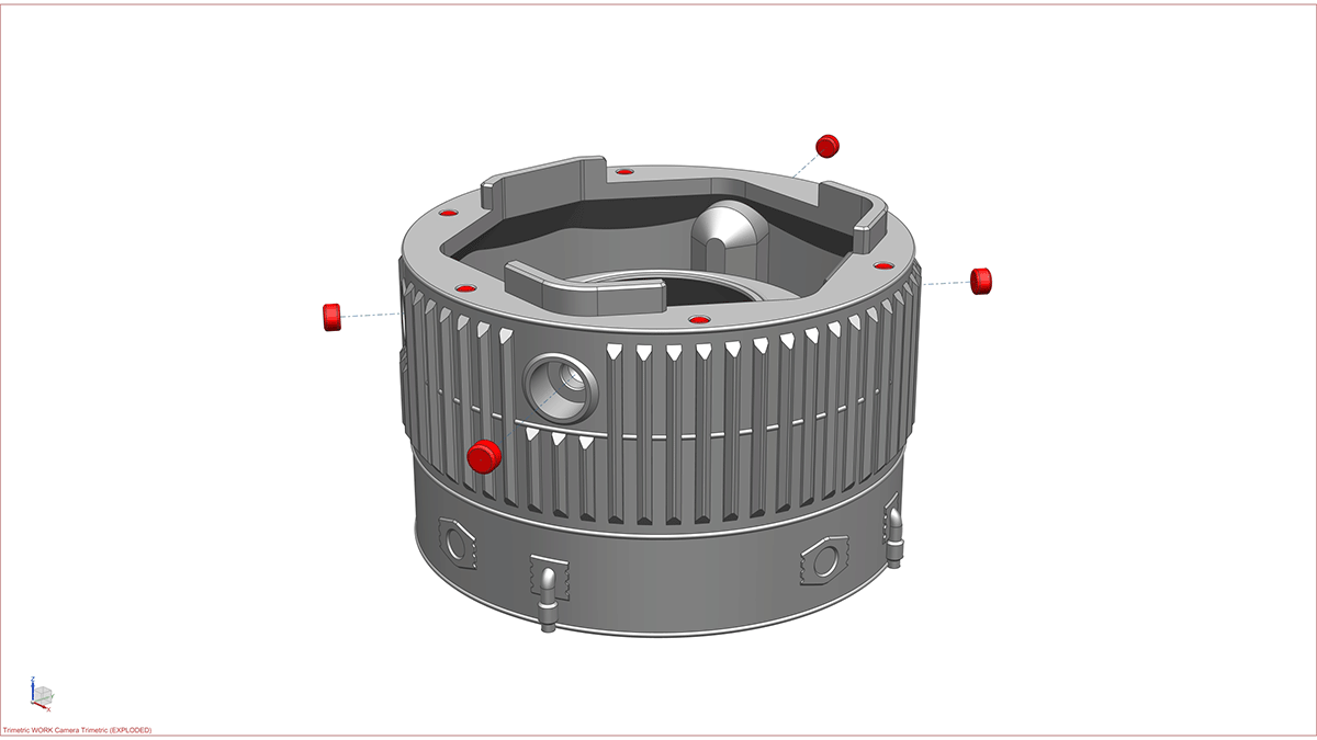
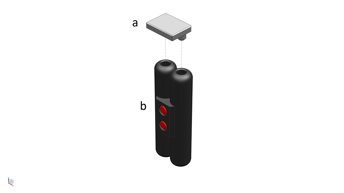
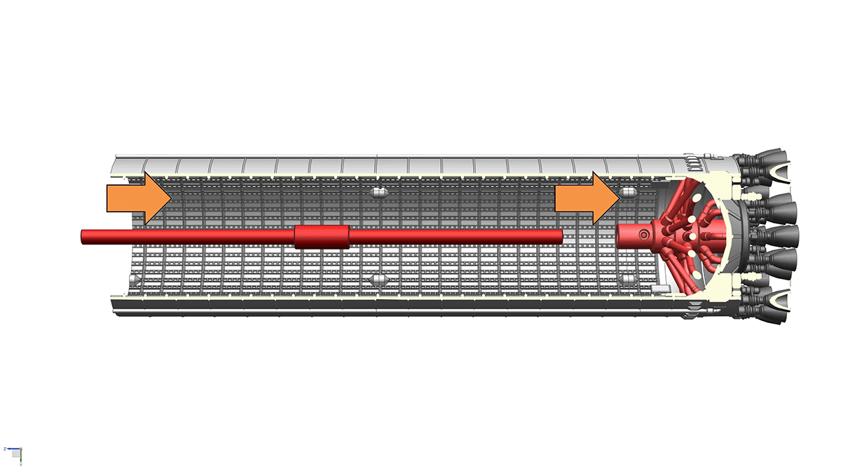
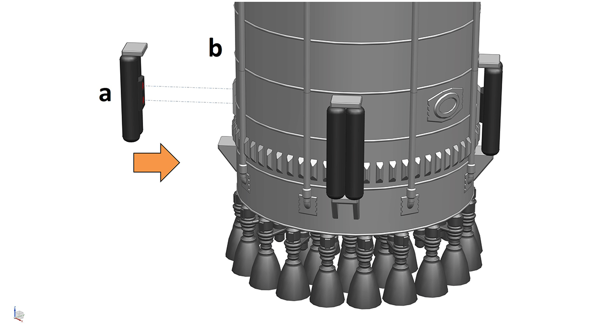
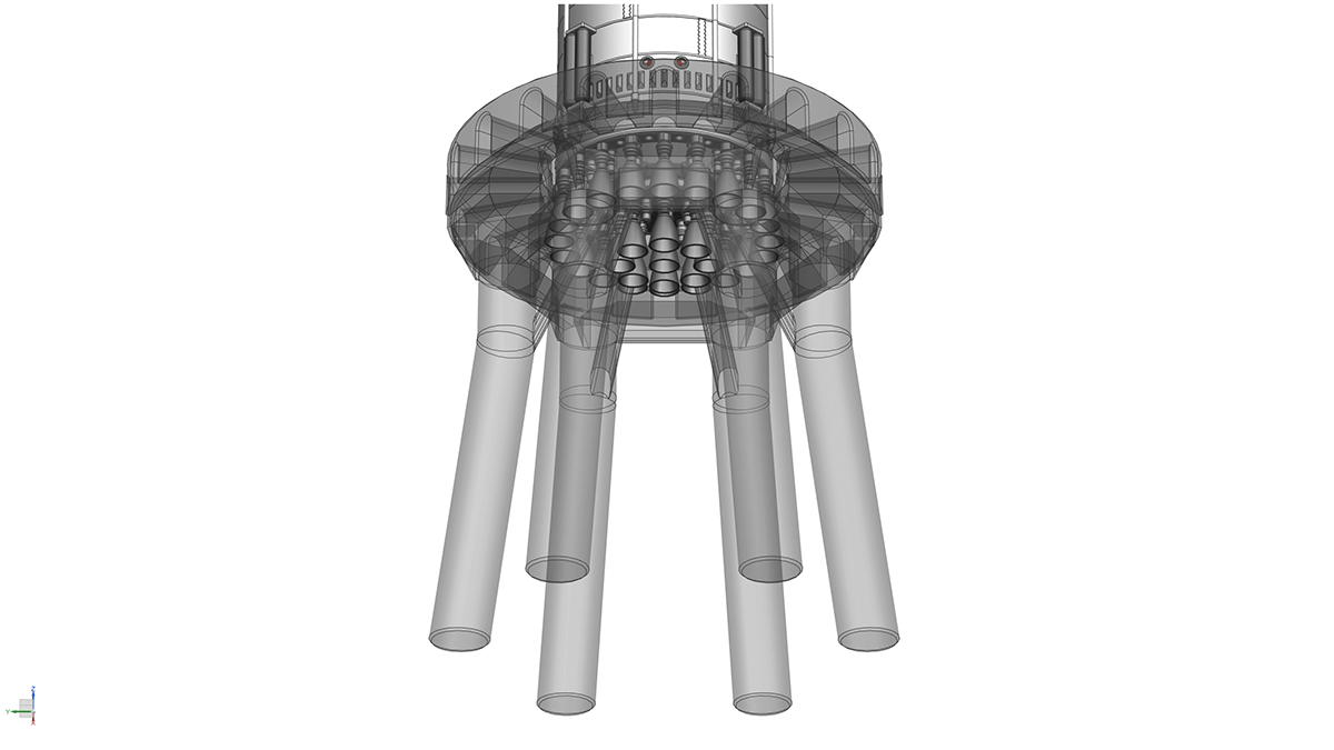
Hi! i just printed and assembled my booster, looks great! I have one question though. On the last CH4 Distribution Pipe there is a small magnet on the side, I suspect this has something to do with the 2 holes in the side of the booster, but I cannot find any instructions on what to place on that magnet. Do I have something missing or is that for a future planned upgrade?

2
0
Please vote & feedback on this product :)x